Fullagar Diesel Generating Plant at Napier, The


(i)
SUMMARY
This publication covers the historical background and technical information relating to the 600 horsepower 400 kilowatt Fullagar diesel generating plant which operated at the Napier City Council’s Power Station from 1925 until 1970.
The Fullagar-type engine has opposed pistons and vertical cylinders arranged in pairs. Its unique feature is the diagonal connecting rods which attach the top piston of one line to the bottom piston of the adjacent line.
It is believed to be the only plant of its type in New Zealand and will be the principal exhibit in the Hawkes Bay Museum of Technology when it moves its activities into the former power house building in Faraday Street, Napier, New Zealand.
The Author H R (Ray) Matthews, FIPENZ, MIEE was City Electrical Engineer Napier 1958-1978
The Sponsor Bay City Power was previously the City Electricity Department and prior to
that the Municipal Electricity Department, which owned and operated the plant on behalf of the Napier City Council.
ACKNOWLEDGEMENTS
The writer wishes to record his thanks to:
– former staff members for their contribution; the names listed alphabetically are:
Alec Howse, Jack Isles, Dick Larrington, Alan McRae, Ted Marcroft, George Metcalf, Pat Sullivan and Ian Webster;
– the Committee Clerk and Records Officer at the Napier City Council;
– Mrs Pat Roddick, Reference Librarian, Engineering Library, University of Canterbury.
– Trevor Stewart, Acting General Manager, Bay City Power, for providing funds for the reproduction of this article;
– Bob Gordon, Bay City Power, for looking out drawing office records;
– Yvonne Matthews, reading through the script and making corrections;
– Sue Shields, Bay City Power, for the typing;
– Mrs E D P Symons, Archivist, Institution of Electrical Engineers, London;
– K Hawker, Editor, Daily Telegraph, Napier, for permission to use clippings;
– Robert Cox, Walditch, Dorset, for information on Willans Works etc
– Stephen Evans, Science Museum London for information on H F Fullagar;
– Joy Axford, Curator of Archives, HB Cultural Trust, Napier;
– Richard Matthews, for producing the drawings on Page IV.

(ii)
CONTENTS
Page Number
Introduction 1
Purchase of AC Generating Plant 2
Description of Fullagar Engine 2
Pistons 3
Fuel Injection 3
Lubricating System 3
Cooling Water 4
Starting Method 4
Bulk Fuel Tanks 4
Exhaust Arrangement 5
The Alternator 5
The Price 5
Hours run 6
Initial Running of the Plant 6
Standby Operation 7
Napier Earthquake 1931 8
Feedback 1941-1953 8
Power Shortages 1958-1960 9
An Early Call 9
Wrong Grade of Oil 9
Starting Difficulty and Electric Starting 10
Starting Misadventure 10
Financial Return 10
The Demise 11
References 12
Appendices (listed on next page)

(iii)
APPENDICIES
1. Notes on Explosion and Runaway 13
2. Generation and Financial Results 14-17
3. Fullagar Plant Data 18
4. Borough Electrical Engineers Reports
i Plant following the earthquake (2.10.35) 19
ii Cost of Generating January-March 1928 21
iii Generating Unit (28.10.26) 22
5. History of Napier Municipal Electricity Department (Extracts) 23
6. English Electric Diesel Catalogue (Extract) 24-26
7. Fullagar Oil Engine Operators Manual (Extract) 27-28
8. English Electric Drawings for Napier Plant 29-36
9. Photographs from Daily Telegraph Clippings 37-40
10. Extracts from Council Minute Books (including paper clippings) 41-45
11. Operating Staff 46
12. Comparison; the Fullagar and a 1991 diesel engine 47
13. Notes on the English Electric Co & HF Fullagar MA 49-51
14. City Electrical Engineers Report of 4 February 1971
Reliability of Supply and Standby Generator Replacement 52-54

(iv)
OPPOSED PISTON ENGINES
Internal combustion engines with opposed-piston designs have been built in several different configurations including the Junker, Oechelhauser, Doxford and Fullagar. The two latter types are illustrated in the diagram below.
In the Kensington Science Museum there is a sectional model of a Fullagar-type engine with a label “Between 1916 and 1920 Cammell Laird adapted this for Marine Propulsion”.
SIDE ROD
TOP PISTON
EXHAUST
INLET
DOXFORD USES SIDE-RODS
DIAGONAL ROD
CROSS HEAD
TOP PISTON
FULLAGAR USES DIAGONAL RODS
COMPARISON OF TWO TYPES OF OPPOSED-PISTON ENGINES

– 1 –
INTRODUCTION
The 600 horsepower Fullagar diesel engine and its 400 kilowatt 3,300 Volt alternator operated in the power house in Faraday Street, Napier, New Zealand from 1925 until 1970.
The plant has been donated to the Hawkes Bay Museum of Technology where it will remain in its original location. The Museum has arranged to lease the old power house building from the Napier City Council.
The purpose of this publication is to record the history of the Fullagar plant.
Because it is 21 years since the plant was last operating, some of the records no longer exist. Fortunately a number of former staff members were able to contribute information about the plant.
The engine was built by the English Electric Co Ltd at its Willans Works, Rugby, England in 1923.
Only two engines of this size were ever built). The other was used by the English Electric Company at its works at Rugby from 1922 until 1950 and subsequently placed in the Company’s Museum when it was placed on display on the lawn where it deteriorated. It was finally scrapped (27) about 1980.
It is believed to be the only diesel engine of its type used in New Zealand and is possibly the only surviving Fullagar engine in the world.
What appears to be the first trial run for the acceptance test for the Napier plant took place on 4 September 1925 when the following entry appeared in the log book:
“Trial test was run this day: engine ran satisfactory on full load for eight hours: trouble then developed and the engine lost load: engine picked up load again and continued running on full load for another three hours.”
It was not until 21 April 1927 that the following entry appeared in the log:
“Fullagar ran the trial test with satisfactory results, everything OK.”
By this time preparations were in hand to receive power from the Government’s hydro-electric station at Mangahao, near Shannon, 200km south of Napier. In fact only two months later, on 1 July 1927, hydro-power was received at Napier.
As the hydro-supply contract provided that existing plant be retained only for standby purposes, it might be expected that the Fullagar plant would have not been required for much running and eventually would have been retired in debt.
This was not to be the case as power shortages in successive years made frequent demands on the running of the plant. The shortages were due to ‘dry’ years and insufficient hydro plant to meet the load growth. Details of the plant running are given in Appendix 2 on pages 14-17.
Technical data on the plant is detailed in Appendix 3 on page 18 and outline drawings appear in Appendix 8 on pages 29-36.

– 2 –
PURCHASE OF AC GENERATING PLANT
The Napier Borough Council’s initial generating plant was installed at the Faraday Street power house in 1913. It provided electricity for a tramways system as well as power and lighting for the people of Napier.
A 230/460 Volt direct current supply was obtained from three generators driven by gas engines which were fuelled by producer gas (from coal) that was manufactured on site (1)
Subsequently additional dc plant (both diesel and gas engine driven) was installed to keep up with the demand for electricity.
In 1922 Consulting Engineers (2) were commissioned to review the position having in mind the possibility of hydro-electric power being available from the Government Stations already being constructed in the North Island.
The Consultants recommended that a 600 horsepower diesel engine with a 400 kilowatt 3,300 Volt alternator be purchased together with two motor generators each of 200 kilowatts in order to convert the power from ac to dc and vice versa.
The Napier Borough approved the recommendations (3) and subsequently a tender was let (4) for supply of the Fullagar diesel generator set, manufactured by the English Electric Co.
DESCRIPTION OF THE FULLAGAR ENGINE
The Fullagar engine operates on a two stroke cycle. Pairs of cylinders are placed close together to form a unit and there are two opposed pistons in each cylinder. The upper piston in one cylinder is connected to the lower piston in the adjacent cylinder by diagonal connecting rods. In this way the two pistons in one cylinder are compressing while the adjacent cylinder is expanding.
It is understood the design by H F Fullagar stemmed from marine applications where floor space should be minimized. Cammell Laird & Co of Birkenhead, Liverpool, England obtained the rights to develop and use the Fullagar principle for marine oil engines (21, 22).
The diagonal connecting rods between adjacent cylinders are connected to crossheads to take the lateral forces at both the top and bottom cylinders. The top crossheads are enclosed so that they act as pistons for the scavenge-air pumps which supply the inlet air under pressure (super-charging).
The exhaust air ports are uncovered while the scavenge-air inlet ports are still open so that the scavenge air sweeps completely through the cylinder.
The inlet and exhaust port are machined at the top and bottom of the cylinder liners while the centre portion of the liner forms the combustion chamber. In the wall of the combustion chamber there are two fuel injectors and an air-starting valve.
The liners are fitted with inward springing scraper rings at each end which bear on the piston skirts.

– 3 –
PISTONS
The crown of the piston is made from forged alloy steel while the skirt is made from cast iron. Four compression rings are fitted. The steel crown is oil cooled, the oil being fed to and from the crown by telescopic tubes. The original pistons had flat crowns but a full set of replacement pistons supplied in 1959 by English Electric were manufactured with concave crowns.
During World War II some replacement pistons had been on the coast for at least three months and could not be located. In order to keep the plant running Nivens at Ahuriri, Napier, reconditioned some of the older pistons cutting off the crowns and welding them to pistons with good skirts.
FUEL INJECTION
Fuel injection is by high-pressure air blast with fuel supplied at low pressure to the air blast valves on each cylinder.
The fuel feeds by gravity from an elevated service tank through the filter to a bus-pipe to the injection pumps. There is one cam-operated injection pump on each cylinder and these can be individually adjusted to equalise the load over all the cylinders. This is done by monitoring the exhaust gas temperature on each cylinder or by comparing indicator diagrams.
The two fuel injection points on each cylinder are opposite each other to promote thorough mixing of the fuel with the air.
All cylinders have a valve for recording pressure on a drum recorder to produce an indicator diagram.
The quantity of fuel is regulated by the governor.
LUBRICATING SYSTEM (7)
An auxiliary electrically driven pump supplies oil to the bearings, crossheads and to the piston crowns before starting. This ensures that the pistons do not overheat before the oil supplied by the crankshaft-driven pump has built up pressure.
Oil from the piston crowns is returned to the sump via a tundish. This provides the operator with a visual inspection point to check both the flow and temperature of the cooling oil returning from individual pistons.
The oil sump strainer and cooler are all accessible from the pit below the engine.
In addition there are sight glasses and pressure lubricators which supply a measured quantity of lubricating oil to the scavenge cylinders and for centre-stroke lubrication for the main pistons.

– 4 –
COOLING WATER
Cooling water was provided from a cooling pond adjacent to the power house building. Water could be supplied direct from the town water or circulated by means of a pump from the pond. Originally there was separate well at Nelson Park (0.7 km away) which provided the cooling water for the power station through lead-jointed cast iron pipes.
A separate outlet from each cylinder jacket to a tundish on the side of the crankcase allows the operator to check the flow and temperature of the discharge cooling water from each cylinder jacket.
STARTING METHOD
Starting is provided on two of the cylinders from ‘air-start’ valves supplied with compressed air through cam-operated service valves fitted to the cam-shaft. Air is admitted to the cylinders through automatic air-starting valves fitted in the combustion chambers. Air is provided from two air starting bottles charged to 1,200 lb/square inch.
Kerosene is used for starting purposes; diesel fuel is used once the engine has started.
Fuel injection pressure is provided from a separate air bottle.
Once the engine is running, compressed air for injection (and for filling the bottles) is provided from a three-stage compressor fitted at the end of the crankshaft. An unusual feature of the compressor is that the output pressure is regulated by throttling the air intake. It also uses a multi diameter cylinder and piston to provide a three stage compression.
The alternator was arranged for starting the engine from June 1962 and this is described later.
BULK FUEL TANKS (5)
Before 1959 six 1,600 gallon tanks were used to store the ‘heavy’ diesel fuel, which was sent from Wellington by rail tanker.
From 1958 there was no advantage in using the ‘heavy’ fuel. Standard diesel fuel was used from local supplies and the storage reduced to two 1,600 gallon tanks.

– 5 –
EXHAUST ARRANGEMENT
From the manifold the exhaust gases are discharged into a concrete expansion chamber) outside the building. From there the gas is discharged to the atmosphere through a vertical pipe about 30 feet high.
THE ALTERNATOR
The 400kW 3,300 V alternator was built by the English Electric Company at its Siemens Works Stafford. The 30 pole machine is 10 feet in diameter and the lower portion of the stator is in a pit and extends 3 feet below ground level. Both the engine and the alternator are required to provide 25% overload for one hour after running at full load for eight hours.
The alternator was supplied without an engine-driven exciter. Initially there would have been dc available for excitation from existing plant although a small motor-generator was provided.
However, to provide power ‘from cold’ (ie when no other power was available) a belt-driven exciter was powered from a pulley at the end of the shaft. This exciter was the dc generator which supplied power to the Municipal Theatre from 1912 to 1928. It was also presumably used as the exciter from the mid 1930’s.
THE PRICE
The original contract price (4) was quoted as equivalent to $24,500 plus the 3,300V oil circuit breaker at $544. (8) The total price was approximately $25,000.
When the power house building was extended in 1920 sufficient extra space had been allowed for additional plant and the Fullagar was able to be accommodated without further extension. It is likely that the compact design was a factor in its selection.
The English Electric Company contract provided for the services of an engineer to supervise the erection of the plant.
Other than the fuel tanks (5) at $646 it is not known what other installation costs were incurred. Most of the labour would have been provided by power house staff and the cost of this was probably regarded as a part of salaries and wages included in the running costs of the station. There would have been some costs for the concrete work for the pits for the oil sump, the alternator and the exhaust expansion chamber, and the fuel tank installation. The latter consisting of a concrete pit, half the height of the tanks and a frame with an iron roof overall.

– 6 –
HOURS RUN
There was no hour meter on the plant, and records of running time before 1940 are not available. An estimate has been made for the kWh generated up to 1931 using the value of the fuel purchased. A 100kW diesel plant was operating at the same time, some guessing was needed to provide an answer.
A total running time to 1970 is estimated at 27,000 hours. Details of this are set out in Appendix 2, on pages 14-17.
INITIAL RUNNING OF THE PLANT
The plant was ready for shipment in January 1924 (11) and arrived in May at the same time as the erection engineer (12)
It is probable no electricity was generated by the plant before March 1925, although the engine may have been tested (17) “The first entry in the log book is August 1925 before the unsuccessful test run of September 1925.
The records (9) show at 31 March 1925 the installed capacity of the generating plant was 830kW and the maximum load was 810kW so that without the Fullagar there was no plant capacity to meet further load growth.
George Metcalf who was an electrical inspector at the time the plant was installed, recalled that there was trouble with the crossheads becoming hot and that additional cooling water had not eased the problem.
When the load was increased more heat would be generated on the friction surfaces of the crossheads at the end of the diagonal connecting rods. This in turn would mean that, if this heat was not conducted away in the oil, then the crosshead would seize up.
This problem still existed in the 1960’s if the plant was operated over about 350kW for a prolonged period.
George also noted that much of the running was on light load mainly supplying the Taradale Town Board and the Hawkes Bay Electric Power Board (HBEPB). Both of these loads were supplied at 3,300 Volts ac and the Fullagar generated at this voltage. When it was not generating, the ac load could be supplied from the de plant via the motor-generators.
By March 1926 the installed plant had increased by 400kW to 1,230kW. The maximum demand within the borough in that year was 988kW. The additional plant provided for growth in the borough’s load and for power supplied to the Power Board and the Taradale Town Board both of which relied on the borough for their initial power supply. The energy supplied to the two boards is listed in the following table.

– 7 –
Energy Supplied to Taradale and HBEPB compared with Fullagar Generation
Year ending 31/3 Taradale kWh HBEPB kWh Total kWh Fullagar Generation kWh
1926 56,941 8,700 65,641 312,000 (est)
1927 78,349 15,525 93,874 378,800 (actual)
The plant was required to run for one hour at 25% overload to pass the acceptance test incorporated in the British Standard. It seems likely that this was the major stumbling block before the plant was accepted.
Inspection of the log book shows that all the cylinder liners were withdrawn between November 1925 and April 1926. Some of the cylinder liners were recorded as having been cracked.
A further 12 months of running under the supervision of. the manufacturers (18) preceded the satisfactory trial test recorded on the 21 April 1927.
STANDBY OPERATION
Hydro-supply commenced on 1 July 1927. Subsequently the plant would only be used for standby purposes and therefore reduced running was expected. However, this was not necessarily the case.
First there were numerous interruptions to the hydro-supply. In fact, in the first three months, there were 21 interruptions and three arranged shut downs (15) totalling 13 hours 41 minutes. Such interruptions also upset the tram service.
Secondly there were water shortages which limited the generation of hydro-power. Because of this the Napier plant, as well as other generating plants in the lower part of the North Island, were brought back into service over the summer of 1927-1928. The Napier plant generated 1,337,920kWh over this period and the Fullagar contributed about 440,000kWh to this output.
The cost of this generation was charged to the Government and the average price was 0.78 cents/kWh generated. By comparison, the average cost of hydro-power was 0.49 cents/kWh for that year.
Generation in Napier continued because of shortages until the Waikaremoana hydro-plant began commercial production at the end of January 1929 (13) . For some time after this the equipment. was not often run.
As the gas-manufacturing plant took about six hours to get into operation from ‘cold’ the gas engines probably did not run again before they were finally put out of action by the 1931 earthquake. The gas-manufacturing plant was however maintained in a ‘warm’ condition for standby purposes until the dc load could be reduced to 300kW (19) This amount of power could be supplied by the motor-generators from the Fullagar’s ac supply.

– 8 –
About 18 times between February 1929 and January 1931 the Fullagar was started either because of power failure or arranged shutdowns. During the day and evening the Fullagar could have supplied the trams and other important loads, but not the needs of many other consumers.
NAPIER EARTHQUAKE 1931
The earthquake of magnitude 7.9 struck Hawkes Bay at 10.46 a.m. on 3 February 1931. The Government electricity supply failed immediately and was not restored until two days later.
Although the Fullagar plant was regarded as serviceable, it was not used because of the precarious state of the power house building. The next day the walls were temporarily shored up by Navy personnel.
Jack Isles says that when a temporary supply of hydro power became available it was limited to essential services such as water pumping.
He recalls a decision was made to run the Fullagar each night until 11.00 p.m. to provide some street lighting and this was favourably commented on by many of the residents, particularly the homeless in the camp at Nelson Park.
Once more the Fullagar refused to start, and the compressed-air supply was exhausted, Colin Stewart, Assistant Engineer, removed the motor from one motor-generator set and using a belt was successful in starting the Fullagar (20)
There was little running of the plant from 1932 until the war-time shortages from 1941 onwards.
FEEDBACK 1941-1953
A general power shortage started early in World War II and continued for some years afterwards. The Fullagar was back in service for another 12 years.
From January 1941 the Fullagar was often in service up to 16 hours a day. This was under a ‘feedback’ contract with the Public Works Department (as it was known at that time) which paid the costs. Power generated went into the ‘pool’ and was re-sold at the standard price for ‘bulk power.
Over the 1941-1953 period a total of 7.2 million kWh were generated and the equivalent of $139,800 (14) was paid for this.
If, however, there was a power failure or planned shut-down, no claim could be made for ‘feedback’. On one occasion during a planned shut-down between about 5.20 a.m. and 7.20 a.m. Sunday, 23 February 1941 the Fullagar supplied the whole Napier load (with water heating off). No doubt it was the last time that this would have been possible.

– 9 –
POWER SHORTAGES 1958-1960’s
When power shortages loomed again in 1958, the State Hydro Electric Department (as it was then known) decided that the cost of running the Fullagar was too great to continue to use it for ‘feedback’ purposes.
Representations were successful in allowing the Fullagar to be run by the Municipal Electricity Department at its own expense to supplement its allocation. The amount of energy was allocated on a weekly basis and the base figure was reduced according to water available for hydro generation. Typically the amount was 80% to 90% of the base allocation.
It was possible to supplement the weekly allocation up to 15% by running the plant 60 hours a week, although this might be exceeded when the going was tough.
Provided the plant was generating over the ‘peak’ period the reduction in bulk supply charges helped to offset the additional cost of running the plant during restrictions.
If 400kW could be shaved off the ‘peak’ in each of the four quarters the reduction in bulk supply charges amounted to $12,000 per annum at that time.
When the shortages eased the Fullagar continued operating for peak reductions until the alternator windings failed early in 1970.
AN EARLY CALL
Maintaining the consumption within the allocation was not without its problems. The weekly allocation finished at 8.00 a.m. each Monday.
On one of those Monday mornings in 1959 the control room operator, Harry Harris, rang the writer at 5.00 a.m. to say we were ahead of the target to keep within the allocation. A taxi was called to pick up Charlie Wilkes, the Fitting Shop Foreman (he didn’t have a phone) and by 8.00 a.m. the generator had produced enough energy to be exactly on target. Naturally everybody was extremely happy.
WRONG GRADE OF OIL
The lubricating oil used was a very heavy grade of marine oil supplied by Mobil and known as Number 3 Marine Oil DTE. Approximately 270 gallons were needed to fill the system.
About 1960 the Council decided to purchase all its petroleum products from one supplier. As a result a 44 gallon drum of SAE 30-40 motor oil was delivered and the system topped up by the operator without questioning the change. ‘
Within an hour the engine had seized up and several days were spent on maintenance and a change of oil. The saving through the processing of one cheque by using one supplier proved rather costly in this instance.

– 10 –
STARTING DIFFICULTY AND ELECTRIC STARTING
The engine was always difficult to start in cold weather. No provision had been made for electric heating elements to keep the water jacket warm. When the use of the engine was contemplated it was normal to leave radiant electric heaters adjacent to the combustion chamber as a starting aid.
If both starting bottles were discharged before the engine fired there was panic and delay. Additional air had to be obtained and then there was the slow process of filling the empty bottles. The situation was even worse when Industrial Gases closed their manufacturing plant in Napier as supplies were not always in stock.
For the successful use of the plant for ‘peak chopping’ it was essential to have reliable starting.
In June 1962 it was decided to try starting the engine using the generator as an induction motor. It worked successfully but it did put extra stress on the windings.
The idea was to get the engine moving on the first air bottle and to close the power onto the generator through a reactor to limit the current. The second air bottle plus the power would accelerate the engine sufficiently for it to fire.
STARTING MISADVENTURE
In May 1966 the staff experienced a rather frightening event while starting the engine. It began to accelerate well above the normal speed. The exhaust pipe broke just beyond the manifold, producing terrific noise and much smoke. This is described by Ian Webster in Appendix 1, page 13.
FINANCIAL RETURN
Had the Fullagar been intended to operate as a main generator and had it taken its share of the load, it could have been expected to generate about 1 million kWh per annum. This amount had been exceeded only in the three years (1951-1953).
However, should the Fullagar not have been available in 1926 and 1927 it would have been impossible to keep up with load growth. The problem was not solved when hydro-power became available because all the generating plant was used most of the time until January 1929. The actual amount of money received for this is not known but covered all the costs including depreciation (16).
The amount received for ‘feedback’ in 1941-1953 was $139,680. For the period 1958-1970, when the plant was used for peak cutting, an amount of $111,677 is estimated to have been reduced from the bulk supply account. The running cost of this period is stated as $37,226 (14), thus providing a gross surplus of $74,451 for 12 years.

– 11 –
It could reasonably be said that the Fullagar purchase had been financially successful for the $25,000 initial investment.
The total energy generated is estimated at nearly 9.8 million kWh, which corresponds to about 27,000 hours running.
THE DEMISE
The use of the alternator for starting had no doubt put extra stress on the windings. As well as this the pit in which part of the alternator was located occasionally filled with water and windings had to be dried out before use.
A winding failure had occurred in February 1970 and the cost of repairs was covered by insurance.
However, when a complete failure occurred during starting in May 1970 it was decided that the only solution was a re-wind. An amount exceeding $11,000 was required for this. (23) While this could have been justified economically it was a question of whether it was worth “putting a new handle on the old axe’.
An investigation of the purchase of a mobile plant, was authorised in February 1971 but a suitable one was not found at the time. (23)
The Fullagar’s successor, the high speed diesel engine, usually runs more than seven times faster; is about one-tenth the weight; starts the first time at the touch of a button; and into today’s values is about one-fifth of the cost.
So the Fullagar stands as an exhibit of a dinosaur in a new era of diesel generating plants.

– 12 –
REFERENCES
1. D H Hastie (1951) Napier Municipal Electricity Department, NZ Electrical Journal June 1951, page 483, Extract P 23.
2. Council 25 June 1922 Report in HB Herald 26 June 1922 see appendix 10 page 41.
3. Council 14 August 1922 Report in paper 15 August 1922 see appendix 10 page 41.
4. Council 23 July 1923 Report in paper 24 July 1923 see appendix 10 page 42.
5. Council 09 June 1924 Order for fuel tanks see appendix 10 page 42.
6. Refer to Drawing R472/.328 see appendix 8 page 31.
7. Refer to Drawing appendix 8 page 34
8. D H Hastie; Report of 2 October 1935 appendix 4 page 19.
9. Annual Statistics – Public Works Statement Report of Chief Electrical Engineer.
10. Table 2 Appendix 2 page 16.
11. Council Minutes January 1924.
12. Council Minutes 12 April 1926 Ref to Appendix 10 page 42.
13. Public Works Statement 1929 Report of Chief Electrical Engineer Page 25 “end of January this unit started to carry commercial load – Napier being the first to receive supply from this station (Waikaremoana).”
14. Table 1 appendix 2 page 14-15.
15. Power House Superintendent’s report of 6 October 1927.
16. Borough Electrical Engineers report of 11 July 1928 refer to appendix 4 page 21.
17. Trams and Electric Lighting Committee 11 March 1925. Agenda notes for Chairman for discussion with Mr McFarlane (presumably E E Co).
18. Trams and Electric Lighting Committee 29 March 1927 Refer appendix 10, Page 44.
19. Report of Town Clerk & Bor. Electrical Engineer of 28 October 1926 appendix 4 page 22.
20. Verbal communication from George Metcalf.
21. The Cammellaird [Cammell Laird] – Fullagar Marine Diesel Oil Engine: Engineering (London) 30 January 1920 Pp 144-148.
22. The Cammellaird – Fullagar Marine Diesel Oil Engine: The Engineer (London) February 1920 Pp 107-110, 132-133 (letters to Editor appear in eight subsequent issues).
23. H.F. Fullagar (1914) Balancing of Internal Combustion Engines: Proc. Institution of Mechanical Engineers (London) Pp 559-578 (The Fullagar engine is described on Pp 568-569).
24. City Electrical Engineers Report of 4 February 1971 – Reliability of Supply and Standby Generator Replacement. See Appendix 14, Page 50.
25. Jones, R & Mariott, D: Anatomy of a Merger: A History of GEC, AEI & EE. pp 129-130.
26. Engineering (London, 4 July 1930, pp 7-10
27. Robert Cox of “Hillcrest”, Lower Walditch Lane, Walditch, Dorset, letter of 22 September 1991.
28. Obtituary [Obituary] H F Fullagar: Proc North: East Coast Institution of Engineers & Shipbuilders Volume 33 (1916-1917) pp 287-288.
29. Venn: Alumni Cantabrigiensis 1752-1900, p 587

– 13 –
APPENDIX 1
Notes on explosion and runaway of Fullagar Diesel – by I G Webster March 1991
Date probably May 1966.
“I was in the City Electrical Engineer’s office at Faraday Street when we heard the Fullagar start up. There was the usual ‘backfire’, but this time the explosions continued as the machine sped up. We ran to the power house and could see clouds of black oily smoke coming over the roof; there were four men coming out at a run. When I reached the governor to cut the fuel off it had already been tripped by the operator, but the engine was running above normal speed and climbing. The foreman fitter, Cliff Sant, had come in through the back door and was cutting off the injection air when I got to the operating position. The engine then ran down and stopped.
The cause of the runaway was a broken piston-crown cooling oil pipe (about 12mm bore pipe) which allowed the cylinder to become partially filled with oil when the cooling oil was being circulated prior to start-up. When the engine was turned over to start some of the oil was squirted out through the excess pressure relief valves on the cylinder and some of it was forced out into the exhaust system where it exploded and destroyed a large water-cooled cast iron bend section in the exhaust pipe just behind the engine. The broken pipe belched out flames, oil, smoke and hot water until the engine was stopped. Cooling oil being pumped into this one cylinder provided more than enough fuel to accelerate the engine even after the diesel fuel had been cut off.
The engine was needed to cut peak load and repairs started immediately. The faulty piston was pulled out and the broken pipe replaced. A new exhaust system between the engine and the underground muffler was made using two 6″ water pipes connected to the main engine system by a large steel flange. The new section was not water cooled like the original. The machine was out of service for 8 days.
The main effect, apart from the loss of generation, was the amount of oil deposited on cars and some houses in the area. The whole incident probably lasted only about 5 minutes.”

– 14 –
APPENDIX 2
TABLE 1
FULLAGAR DIESEL GENERATOR
GENERATION AND FINANCIAL RESULTS
1 2 3 4 5 6
Year ending 31 March Operating hours Fullagar generation kWh (1)
RESULTS
Received for feedback $ (4) Value of peak chopping Running Cost (5)
1925 NIL
1926 312,000
1927 378,800 (2)
1928 378,000 9,631 (3)
1929 227,000
1930 50,000
1931 10,000
1932 3,000
1933 0
1934 3,000
1935 0
1936 270
1937 630
1938 600
1939 730
1940 5,460
SUB TOTAL 1925/1940 1,370,290
1941 97,300 1,188
1942 36,124 460
1943 112 93,852 1,212
1944 938 373,987 6,398
1945 578 224,965 3,512
1946 1,362 534,396 8,500
1947 1,493 583,382 8,766
1948 2,209 796,596 13,940
1949 1,130 442,194 7,880
1950 67 25,989 576
1951 3,185 1,314,807 30,368
1952 3,304 1,464,125 29,242
1953 2,798 1,212,759 27,638
1954 3 521
SUB TOTAL 1941/1854 7,202,297 139,680 = 1.93c/kWh

– 15 –
Table 1 continued
1 2 3 4 5 6
Year ending 31 March Operating hours Fullagar generation kWh (1)
RESULTS
Received for feedback $ (4) Value of peak chopping $ Running Cost (5) $
1958
1959 175,371 6,734 4,090 (est)
1960 74,280 13,742 4,034
1961 91,395 5,866 2,206
1962 116,385 6,114 2,726
1963 119,640 8,194 2,598
1964 159,260 8,446 3,790
1965 51,547 7,810 2,442
1966 83,270 10,434 2,270
1967 85,050 12,048 3,270
1968 84,760 14,515 4,900
1969 40,700 8,582 1,891
1970 80,370 9,210 3,270
1971 580
SUB TOTAL 1958/1971 1,162,608 111,677 37, 226
GRAND TOTAL 9,735,195 251,357
Estimated hours run 27,000 hours
Notes appear on page 16.

– 16 –
APPENDIX 2 continued
Notes on Table 1
1. Except for 1927 the generating for the years 1925 to 1931 were estimated from fuel purchases. Refer to Table 2 for details.
From 1932 onwards the Fullagar was the only generating plant operating and figures were taken from “Statistics in Relation to Hydro-Electric operation” A.J.H.R. (D4).
2. For generation in 1927 figures from Power House Superintendents report for year ending 31/3/27 dated 22/6/27.
3. For feed back for 1928 from Bor. Electrical Engineers report 11/7/28 includes generation from all the plant. The Fullagar would have supplied about one third of the total.
4. ‘Feed back’ was the amount received for generation from the Government. (PWD/State Hydro) during power shortages.
5. Running costs (1959-1970) do not include overheads and depreciation.
TABLE 2
Estimating the Fullagar Generation 1924-1931
Year ending 31/3 Total Generation kWh Cost of fuels (2) Coal $ Oil $ Fullagar Generation kWh
1924 – 12,516 145 Nil 100kW operating
1925 2,209,000 11,968 298 32,600 (4)
1926 2,659,000 12,196 1,534 312,000
1927 2,961,000 13,522 1,930 378,000
1928 1,257,000 10,090 1,930 378,800
1929 1,198,000 2,833 1,192 227,000
1930 50,000 922 20 50,000
1931 10,000 213 10,000

– 17 –
Notes on Table 2
1. The estimate for the Fullagar generation for the years 1925-1929 is based on the 1926-1927 Annual Report of the Power House Superintendent of 22.6.27. Using the prices for fuel quoted in a report of 11 July 1928 the following comparisons are possible by combining the information in these two reports.
kWh generated 1926-1927 Fuel consumed Price $ Fuel cost $ Fuel cents/kWh
Gas Plant (730kW) dc 2,575,022 3,580 tons (coal) 3.83/t 13,711 0.53
Diesel (100kW) dc 7,528
33,674 gals (oil) 0.05/gal 1,684 0.44
Fullagar (400kW) ac 378,824
Total 2,961,374 15,395 0.52
2. The value of fuel purchased was taken from Annual Accounts although the amount used could be slightly different due to the amount in stock.
3. The amount of fuel purchased for the 100kW diesel in 1924 was assumed to be same for subsequent years and therefore the remaining amount used by the Fullagar. In 1927 386,350kWh were generated for $1,930 of fuel oil purchased which represents 200kWh per $ of fuel purchased. In the report of 22.6.28 fuel oil consumed for 1926-1927 is stated as 33,674 gallons which represents 11.5 kWh/gallon average for both diesel sets that year.
4. Committee Agenda of 10.2.25 refers to “Power House plant now being erected Fullagar switchgear etc”. It’s probable that there was no actual generation before March 1925 although fuel was purchased.

– 18 –
APPENDIX 3
FULLAGAR PLANT DATA
ENGINE: English Electric Co, Willans Works Rugby.
Reference: 4Q IF401 Manufactured 1923.
Type: Diesel two stroke with scavenge (supercharger).
Speed: 200 rpm
Cylinders: 4 bore 14 inches
Stroke: 16 inches x 2 for 2 pistons in each cylinder
Displacement: 9,852 cubic inches, 161.4 litres
Output: 600 hp continuous; 25% overload 1 hour
Flywheel: Diameter 9 feet; weight 8 t (calculated)
Starting: Compressed air – (later electric) kerosene fuel.
Fuel injection: blast air (550 – 940 lb/sq inch).
Compressor: 3 stage with intercooler
Fuel Consumption:
11.5 kWh/gal (with heavy fuel), 1927 average for year
12.5 kWh/gal (light fuel) at 350kW, 1959, test
11.5 kWh/gal (light fuel) at 420kW, 1959, test
Lubricating / Cooling Oil: Capacity approximately 260 gallons
Pressure feed from shaft driven pump plus auxiliary electric driven pump (used before starting)
Oil Cooling: Water heat exchanger.
Oil Grades: Lubricating (from September 1958) Mobil No. 3
Marine DTE,
Cylinders (from May 1959) from DTE No. 4 to Marine DTE 3-D (detergent grade).
Exhaust Temperature: 400kW 520°F; 460kW 570°F
ALTERNATOR: English Electric Co. Siemens Works, Stafford, year 1923
Serial: GL 115s, Size GL 1B6530.
Rating: 500kVA, p.f. 0.8, 3,300V, 3ph, 87.5A, 200rpm
Excitation: 110V, 8.5A, 30 poles.
COMBINED
Weight: 60 tons (guess)
Dimensions: Length: 27 feet (8.2 metres)
Width: 12 feet (3.7 metres)
Height: 15.5 feet above ground (4.7 metres)
8 feet below (1.8 metres)
ANCILLARY EQUIPMENT
Compressed Air: 3 air bottles (2 start, 1 injection)
Lubrication: auxiliary electric lubricating pump
Oil Cleaning: ‘Alfa-Laval’ centrifuge and ‘Stream Line’ filter.
Service Tank (fuel & kerosene)
Fuel pump: (originally semi-rotary hand pump); later electric.
Bulk fuel tanks: originally 10,000 gal; after 1959 3,300 gal.
Exciter: (originally motor-generator about 6kW)
subsequently belt driven ex Municipal Theatre 220V, 182A, 650 rpm (run at reduced speed).
Water Cooling facility: concrete pond and electric circulating pump.

– 19 –
APPENDIX 4
2nd. October 1935
The Town Clerk,
NAPIER.
FILE
22 AUG 1975
History [handwritten]
Dear Sir,
Power Station Plant
Depreciation Allotments
In reference to the above I have to report as follows:
Prior to the earthquake the machinery consisted of the following:-
(1) 1 – 215 H.P. Westinghouse Gas Engine & D.C. Generator.
(2) 2 – 430 H.P. Premier Gas Engines and D.C. Generators.
(3) 1 0 150 H.P. Willans Robinson Diesel Engine and D.C.
Generator.
(4) 1 – 600 H.P. Fullagar Diesel Engine and A.C. Generator.
(5) 1 – Balancer Set
(6) 1 – Battery Charging Set.
(7) 1 – Tudor 580 Volt Battery.
(8) 1 – Kerpley Gas Producer.
(9) 2 – Wilson Gas Producers.
(10) 1 – Gas Holder.
(11) 1 – 25 H.P. Boiler.
(12) Switchboards, Gas Producer and Engine Accessories.
(13) 2 – AC/DC Motor Generator Sets.
According to our 1930 Balance Sheet the capital value of the Power House machinery was set down at £65,542 : 15: 3 plus £4,221 : 0 : 0 for Item 13.
At the time of the ‘quake all the above machinery was in running order but the D.C. Plant and Gas Producer Plant had not been used for some time as we had practically completed the “Change Over” and according to our agreement we could not peak reduce. The quake destroyed Item 7, and this made useless Item 6.
The Commissioners appointed Mr. Climie as Engineer and he had a considerable amount of the Gas Plant dismantled (i.e. Gas Pipes Etc.) and used them for other Borough services. As all the auxiliary motors were D.C. they were dismantled and have since been sold, and later on, the Boiler (Item/11) was sold. This now puts the Gas Plant and Gas Engines entirely out of commission. If the Gas Plant was restored to working condition all the Generators would hev [have] to be dismantled, as they are D.C., and new A.C. machines installed. It is therefore obvious that this machinery cannot be called anything but junk, and in my opinion should be writted [written] off and no allowance made for depreciation.
As it is difficult to find out what this machinery cost I consider that the plant which is capable of use and is used, and for which I am able to find the approximate cost, be allocated into their respective headings for depreciation allotments as per attached sheet.
The depreciation alloted [allotted] in the past amounted to £2790.11.0 and if the above suggestion is carried out the amount will be £1144.19.2 making a saving of 21645.11.3.
Yours faithfully,
(D H HASTIE)
Borough Electrical Engineer

– 21 –
APPENDIX 4 CONTINUED
NAPIER MUNICIPAL ELECTRICITY DEPARTMENT
Dear Sir,
The following statement shows generation costs from January 1st, 1928, to March 31st, 1928 :-
Units supplied to Public Works Department – 1,257,120
Units generated not debitable to Public Works Department – 80,800
Total productive Units generated 1,337,920
COSTS
COAL: 1206 Tons @ £1:18: 4 per ton – £2,311 :10: 0.
FUEL OIL: 44,172 Gallons @ 6d. per gall. – 1,104 : 6: 0.
LUBRICATING OIL: 43 Casks (various grades actual cost) – 446 : 8: 6.
GENERATION – LABOUR: 70 days @ £11:17: 6.
21 days @ £5: 16: 6. 953:11: 6 £4,815:16: 6.
Working cost per productive Unit generated = .86 pence
If a portion of Capital charges are to be debited I suggest, viz:-
Approximate value of plant in service £40,000 @ 5% for 70 days = £ 383:12: 0.
Total cost including Capital charges £5,199: 8: 0.
Total cost per productive units generated = .94 pence.
(Sgd) J. P. WOODSON,
Boro’ Electrical Engineer.
Napier, 11th July, 1928.

– 22 –
NAPIER BOROUGH COUNCIL
To
The Chairman & Members
Trams & Electric Lighting Committee.
Gentlemen,
Generating Unit
In accordance with your instructions we beg to report as follows:-
In view of the fact that Council has practically concluded arrangements to take the whole of the required supply of Hydro-Electric current from Government Supply, through the Hawke’s Bay Electric Power Board, and that current will be available in approximately four months, it does not appear necessary to install additional generating plant.
The arrangements entered into preclude Council from utilising their plant to “peak reduce” therefore any additional plant installed would be as “stand-by” only.
We recommend for Council’s consideration:-
1. That no additional generating plant be installed.
2. That the Fullagar engine and A.C. generator be maintained as a generating unit, instead of the generator being uncoupled and used as a motor generator as originally intended.
3. That the Gas plant be maintained in partial operation as required during the period between hydro becoming available and the D.C. load being reduced to the capacity of the present converting plant and Diesel Unit, viz:- 300 K.W., say during the first period two shifts per day and later one shift per day.
Should there be a failure of hydro supply Council’s position would then be as follows :- Tramways and partial supply service, up to 400 K.W., could be maintained by the Diesel and Fullagar Units, and should the failure be of long duration complete service could be in operation in approximately 6 hours.
It should be noted that the 6 hours required as above will only apply after the Gas plant is completely shut down and that the risk of dislocation of service will be much less during the period the Gas plant is in partial operation.
It is estimated that the cost of the proposed new unit erected complete, together with necessary additions to the Power Station, would involve a capital expenditure of approximately £11,000 and it is not considered that the protection, by way of additional “stand-by” plant, against a partial failure of supply for approximately 6 hours warrants an expenditure of that amount. In any case this additional protection would not be available during the Winter of 1927 and the Public Works Department expect to have Waikaremoana and Mangahao linked together in 1929.
Yours obediently,
(Sgd) JOHN DICK,
Town Clerk & General Manager,
Tramways & Electric Lighting Depts.
(Sgd) J. P. WOODSON,
Power House Supt.
28th October, 1926.

– 23 –
APPENDIX 5
HISTORY OF NAPIER M.E.D.
A
By the middle of 1922, it was realized that further extensions to the power plant would soon be necessary and the Council decided to call in Messrs. Hay & Vickerman, consulting engineers, of Wellington. The late Mr. J. G. Lancaster came to Napier and, after making a thorough investigation, and having in mind that power from Waikaremoana was likely to be available within a few years, recommended the installation of the following:
(a) A diesel engine of 600 b.h. coupled to a 400 kW., 3300 V. A.C generator.
(b) Two synchronous motor convertors, each of 200 kW., 550 V. on the D.C. side with 300 kW., 3,300 V. on the: A.C. side.
The Council adopted the recommendations and called tenders.
The engine purchased was a Fullaga [Fullagar] diesel, and this, with the motor generators and Reyrolle switchgear, was installed in 1925. There were, however quite a lot of teething troubles experienced with the engine and it was not until 1926 that general use could be made of this unit.
The engine is now running under arrangements with the State Hydro electric Department and it is worth recording that in November, 1950, when Sir George Nelson, managing director of the English Electric Company, visited Napier, he said that there were only two engines of this size built. One had been in use at the English Electric works in England and had recently been placed in the company’s Museum. Sir George was, therefore, very interested to see the other unit still running in Napier.
In 1924, the Council, on the recommendations of its officers, again decided to call in the consulting engineers, Vickerman & Lancaster (by this time Mr. Hay had left the firm and Mr. Lancaster had become a partner) to advise them on the advisability of changing over the reticulation from D.C. to A.C.
The local officers had made the suggestion that the work be done in sections spread over years, but Mr. Lancaster recommended the complete change-over and considered the job could be completed in one year. The necessary licence was gazetted in July, 1925, for a period of 42 years from the date of the Gazette and the conditions of the change-over were set out – e.g., who was responsible for the cost of the work, the method of dealing with disputes. The work commenced in 1926 and was carried out by the Council’s staff and supervised by …
B
GENERATING PLANT
The synchronous motors of the two motor-generator sets which were installed in the 1920s were being used for Power-factor improvement, up to the time when the bulk-supply tariff was changed from a kilovolt-ampere to a kilowatt basis, after which the machines were not needed and were sold as scrap when the 3kV system had been dis-mantled in the early 1960s.
The 400 kW Fullagar diesel plant, which had been installed in 1925, had been run at the request of the N.Z.E.D. during power shortages and the electricity generated went into the pool. When Power restrictions were in force again in 1958 the Department no longer required the Fullagar. Arrangements were made for the M.E.D. to run the plant when it chose and it was able to gene- rate electricity for its own consumers and help pay for the cost by a reduction in maximum demand. With the removal of restrictions the generator continued to operate for peak chopping until a winding defect in 1970 prevented further operation. Since then the plant has remained in position but is still unserviceable.
The running of the plant was not without its incidents. On one occasion the governor jammed as the plant was being started and the plant accelerated well above its normal operating speed. The subsequent vibration broke the cast-iron exhaust pipe and the machine exhausted into the building directly from the manifold making a tremendous noise and a lot of fumes. The building was evacuated in a matter of seconds, but the foreman fitter plucked up enough courage to return and turn off the fuel supply.
Extracts
A. D H Hastie (1951)
Napier Municipal Electricity Dept.
NZ Electrical Journal June 1951
Page 483.
B. H R Matthews (1975)
Napier Municipal Electricity Dept. Pt. 2
NZ Energy Journal July 1975
Page 248.

– 24 –
APPENDIX 6
Vol 1, 1947
BRITISH DIESEL ENGINE CATALOGUE
“ENGLISH ELECTRIC”
“English Electric” Fullagar Industrial Diesel Engines
Model designation “Q” Type “Q” Type “Q” Type “Q” Type “Q” Type “Q” Type
Vertical, horizontal or V-form Vertical Vertical Vertical Vertical Vertical Vertical
Two-stroke or four-stroke 2 2 2 2 2 2
Number of cylinders* 6 6 8 6 4 8
12-hr. b.h.p. rating (B.S.I.) 980 1,470 1,960 2,450 3,275 3,500
If pressure-charged No No No No No No
Maximum governed speed, r.p.m. 300 300 300 200 200 214
Cylinder bore, ins. and mm. 14 356 14 334 14 336 19 483 19 483 19 483
Piston stroke, ins. and mm. 16 (2) 406 16 (2) 406 16 (2) 399 22 (2) 359 22 (2) 359
Full-load brake mean effective pressure, lb. per sq. in. 65.6 65.6 65.6 65.0 65.0 65.0
Maximum mean piston speed, […] per min. 800 800 800 734 734 785
Combustion system Direct Direct Direct Direct Direct Direct
Guaranteed full-load fuel consumption, lb. per b.h.p. – hr 0.38 0.38 0.38 0.37 0.37 0.37
Standard starting system Air Air Air Air Air Air
Capacity of crane required for maintenance work 15 tons 15 tons 15 tons 20 tons 20 tons 20 tons
Complete engine weight (dry), lb. and kg. 112,000 30,000 152,320 69,090 287,200 93,900 369,600 167,640 448,000 203,200 448,000 203,200
Overall length, ins. and mm. 179 4,335 250 6,345 299 7,585 322 8,180 402 10,220 402 10,220
Overall width, ins. and mm. 132 3,355 132 3,355 128 3,260 186 4,725 186 4,725 186 4,725
Overall height, ins. and mm. 187 4,745 187 4,745 187 4,745 276 7,010 276 7,010 276 7,010
Fullagar engines are of the opposed-piston type.
THE Fullagar is an entirely British, engine of the vertical, totally enclosed, opposed-piston type, operating on the two stroke cycle, and employing direct mechanical injection of the fuel. A special feature of the Fullagar design is that it has only one crank and connecting rod per cylinder. The engines are built as 4-, 6- or 8-cylinder units in two standard cylinder sizes, known as the “Q” and “R” types.
The method of operation is set out in Fig. 1. This shows a pair of cylinders each having two pistons working in it. Fig. 2 shows a pair of connected pistons with the forces that are actually applied in operation. To overcome the need for two cranks per cylinder the lower piston in the first cylinder is connected to the upper piston in the second cylinder, whilst the lower piston of the second cylinder is connected to the upper piston in the first cylinder (Fig. 2).
Combustion takes place between the opposed pistons A and B (Fig. 1) and causes B to move downwards and A upwards. Piston A sets on the right-hand crank, through the tie rods, also draws up piston D in the adjacent cylinder. Piston B acts directly on the left-hand crank, and draws downwards the piston C in the adjacent cylinder. The power required for compressing the air in the combustion chamber is thus obtained directly from the pistons in the adjoining cylinder, instead of having to be transmitted through the crankshaft. The crankshaft receives two equal and opposite impulses, and the side thrust produced by the tie-rods is taken by the cross-heads F and G. It should be noted that the obliquity of the rods is small, and much less than the maximum obliquity of the usual connecting rods in the ordinary trunk-piston engine.
The lateral forces on the cross-head faces are, therefore, very small. The top cross-heads are so designed and enclosed that they act as the pistons or displacers of the scavenge air pumps on the “Q” size, whilst on the “R” size, separate pumps surmount the top cross- heads.
Bearing Conditions
Because the pressure in the cylinders acts equally on the upper and lower pistons, the forces upon a pair of cranks are virtually equal and opposite at all times, and the main bearings are, in consequence, relieved of load. The pressure between the pistons is taken wholly by steel parts, i.e., the cross-heads, tie-ends, connecting rods and crankshaft, thus relieving the framing of all major stresses. The reciprocating parts are cushioned at each end of the stroke ; for example, in Fig. 1 the pair of connected pistons, A and D, are cushioned upon the down stroke by the compression pressure under piston A and on the up stroke by the compression pressure above piston D. Thus exceedingly smooth running is obtained.
It will be seen that the exhaust ports are uncovered slightly before the scavenge inlet ports, and when the latter open, the scavenge air sweeps right through the cylinder from end to end giving a most efficient scavenge arrangement. With the construction described, each connecting rod is double-acting, and the effort of each crank is uniformly in one direction. A four-crank engine therefore receives four pairs of balanced impulses per revolution – eight in all – and the consequent turning effort is exceptionally uniform.
As the bedplates, which are made of cast iron, are of the flat-base type, they are convenient to handle and facilitate the construction of foundations. The bedplates of the Q size and larger engines are cast in two pieces joined together by bolts and located by fitted bolts. The main-bearing housings are rigidly supported by webs and

– 25 –
“ENGLISH ELECTRIC” BRITISH DIESEL ENGINE CATALOGUE
Sectional views of a six-cylinder Q-type “English Electric” Fullagar engine: the lubrication system is shown in green.
all are bored at one setting, thus ensuring true alignment.
The crankshaft is forged solid from a single bloom of high-grade steel.
For the 8Q and 8R engines, the crank-shafts are made in two halves, registered and bolted together. The cast-iron flywheel is bolted to a flange, which is formed on one end of the crankshaft. Oilways are drilled, and the shaft is machined all over to close limits.
The design of the crankcase, which is made of cast iron, is such that the main and large-end bearings and lower cross-heads are readily accessible. Machined facings are provided to receive the registered thrust guides for the lower cross-heads.
Cylinder jackets are of monobloc construction, and the water jackets for two cylinders are formed in one piece. Each jacket casting is bored to receive the cylinder liners, and large doors are provided to facilitate the cleaning of the water spaces. The cylinder-jacket castings are bolted to the top of the crankcase, and adjacent jackets are bolted together. The cylinder liners are of special cast iron, machined externally for registering with the landings in the jackets. The liner bores have a ground finish. To prevent distortion which might be caused by expansion and contraction, the liners are at the upper end only, and are made a light fit in the lower end of the jacket casing. This arrangement also facilitates withdrawal.
Exhaust and air ports are machined near the top and bottom ends of the cylinder liners. To ensure that no water leakages occur the joints are made with “Dexine” rings which have water, oil and heat-resisting properties. The centre portion of the liner forms the combustion chamber, and is, therefore, adequately and equally cooled. In the wall of this combustion chamber are fitted the two fuel injectors, a relief valve, and air-starting valve. The liners are fitted with inward-springing scraper rings at each end, which bear on the piston skirts, and are easily accessible from the crankcase doors and top inspection covers.
Four “English Electric” Diesel engines; each driving 1,020-kw. alternator.

– 26 –
BRITISH DIESEL ENGINE CATALOGUE “ENGLISH ELECTRIC”
The cross-head guide slippers are faced with anti-friction metal. These slippers take the thrusts due to the connecting rod and cross head tie-rods, thus relieving the pistons and liners of all loading other than that due to the working gases.
In the “Q” type engine the upper piston is bolted to a cast-steel cross-head, which forms a rectangular displacer piston for the scavenge-air pump, the cross-head being fitted with sealing bars to prevent leakage of the displaced air. In the “R” type the upper cross-heads are not used as scavenge-pump cylinders.
The scavenge cylinders are of cast iron, and in the “Q” size, as previously mentioned, they are of rectangular form. These cylinders are cast in pairs and have removable covers. The dividing wall of each pair of scavenge cylinders, against which the main thrust from the upper cross-head is taken, is water-cooled.
In the “R” type, the scavenge pumps are double acting, operated by piston rods attached to the top faces of the upper cross-heads, the cylinders being circular.
The crown of the piston is manufactured from forged-alloy steel, while the piston skirt is of special cast iron. Four compression rings are fitted. The steel-crown is oil cooled, and fitted with a deflector to ensure efficient circulation of the oil; this is led to and from the crown of the piston by a simple arrangement of telescopic tubes.
The hollow gudgeon pin, of the fully floating type, is arranged in the lower cross-head. The pin is case-hardened and is carried in bronze bushes fitted in the cross-head.
The connecting rods are manufactured from 35-ton Siemens-Martin steel, machined all over, and are drilled for the lubrication of the cross-head pin. The top-end bush is of steel, lined with white metal for the “R” type and of phosphor bronze, fully floating, in the “Q” type.
Coupled Cross-heads
The tie-rods connecting the top and bottom cross-heads of adjoining cylinders are rigidly attached, and are manufactured from alloy steel.
The top and bottom halves of the main-bearing shells are lined with white metal, and similar linings are used for the large-end bearings, which are of cast steel. The connecting-rod bolts are of heat-treated alloy steel, and their large diameter provides low working stresses.
From the storage tank, fuel is led through a duplex-type filter to a bus pipe which supplies the individual fuel pumps. The fuel-injection pumps are grouped in pairs, and are operated by cams fitted to a cam-shaft. A fuel pump is provided for each cylinder, and each pump has individual adjustments in order that the correct distribution of load over all cylinders can be accurately maintained. For priming and cutting-out purposes, provision is made for the hand operation of each pump individually. The quantity of fuel delivered by the pumps to the combustion chamber is regulated by the governor in accordance with the load requirements.
Two fuel injectors are fitted to each cylinder in positions directly opposed to each other, thus promoting thorough mixing of the fuel with the air in the combustion chamber.
The centrifugal governor, which is driven by a vertical shaft from the crank-shaft, operates directly on the fuel injection pumps, and is capable of a speed adjustment of 5 percent. above or below the normal engine speed, by hand regulation. Special governing arrangements can be provided, but the standard variation in speed on sudden application or removal of full load is 7 per cent. temporarily and 4 per cent. permanently. Regulation of the fuel is carried out by the angular movement of a shaft, operated from the governor and transmitting movement to the pump racks, thus determining the quality of fuel delivered to the cylinders.
Oiling System
Automatic pressure-feed lubrication to the bearings and cross-heads is provided by a gear-type pump driven from the crankshaft. This pump delivers oil from the sump tank through fine-mesh strainer of the duplex type and an oil cooler, to bus pipes inside the crankcase. Connections are made from these pipes to the crankshaft main bearings and other working parts. For the lubrication of the scavenge cylinders sight-feed pressure lubricators are fitted. Centre-stroke lubrication of the main cylinders is also carried out by these pressure lubricators. For the purpose of cooling the piston crowns, oil is taken from the lubricating pump at a pressure in excess of that required for the main lubricating system. This ensures that the cooling spaces in the piston crowns are kept constantly full.
A lubricating-oil cooler is fitted adjacent to the lubricating-oil pump and strainer.
Verifying Water Flow
A separate water outlet is provided for each cylinder jacket to the common water pipe, each discharging into an open tundish conveniently placed for inspection while the engine is running.
Starting is effected by compressed air through the medium of cam-operated distributors which are fitted to the camshaft of the engine. These distributors admit air at the correct time to the cylinders through the automatic air-starting valves fitted in the combustion chambers. The arrangement provides immediate and reliable starting with the minimum consumption of compressed air. The master air-control valve, which admits air to the distributor, is fixed adjacent to the engine controls.
“English Electric” 8R Diesel engine, 3,500 b.h.p. at 214 r.p.m.

– 27 –
APPENDIX 7
FULLAGAR OIL ENGINE: OPERATORS MANUAL
(EXTRACTS)
DESCRIPTION OF
“ENGLISH ELECTRIC”
FULLAGAR OIL ENGINES.
The “English Electric” Fullagar Oil Engine works on the two-stroke cycle. As shown in the sectional arrangements. Plates I. and II., the two cylinders of each complete unit are arranged as closely together as possible, and two pistons work in each cylinder. The upper piston in one cylinder is connected to the lower piston in the adjacent cylinder by means of two steel rods (oblique rods). Thus the upper piston in one cylinder and the lower piston in the adjacent cylinder, being directly connected, reciprocate together. The method of operation will be readily understood by reference to Figs. 1 and 2, Plate VI., in which Fig. 1 shows diagrammatically a pair of cylinders and cranks from which a complete engine is built up by using two, three or four such pairs; Fig. 2 shows the moving line corresponding to one crank.
Referring to Fig.1, combustion takes place between the opposed pistons A and B and causes B to move downward and A upward. Piston A acts on the right-hand crank through the oblique rods and also draws up piston D in the adjacent cylinder.
Piston B acts directly on the left-hand crank and the shaft thus receives two equal and opposite impulses. The side thrust produced by the oblique rods is taken by the cross-heads F and […] It should be noted that the obliquity of the rods is small and less than the maximum obliquity of the connecting rods so that the lateral forces on the cross-head faces are very small.
The top cross-heads are so designed and enclosed that they act as the pistons or displacers of the scavenge air pumps, an arrangement which avoids complication and reduces the number of parts to a minimum.
As the pressure in the cylinders acts equally on the upper and lower pistons, the forces upon a pair of cranks are equal and opposite at all times, and the main bearings are relieved of load. The pressure between the pistons is taken by such steel parts as the cross-heads, oblique rods, connecting rods and crankshaft, thus relieving the framing of the major stresses. The reciprocating parts are cushioned at each end of the stroke; for example, in Fig. 1, the pair of connected pistons, A & D, are cushioned upon the down-stroke by the pressure under piston A and on the up-stroke by the pressure above piston D.
The scavenge ports are situated at the top end of the liner and the exhaust ports at the lower end. It will be seen that the exhaust ports are uncovered slightly before the scavenge inlet ports, so that when the latter open, the scavenge air sweeps right through the cylinder from end to end.
Forced lubrication is used on all the main parts of the engine. The crankshaft bearings, big ends and top ends of connecting rods, and lower cross-heads are supplied with oil from the main lubricating pump at the compressor end of the engine.
The pistons are oil cooled, the oil supply being taken from the same supply main as that for the bearings, connecting rods, etc.
The oil discharge from these bearings falls to the crankpit and gravitates back to the drain tank under the floor at the compressor end of the engine.
The oil discharge from the pistons is led to a tundish at the back of the engine, and from there flows back to the drain tank above mentioned.
The main lubricating pump draws the oil from this drain tank, and delivers it through strainers and coolers back to the engine. The bearing and piston cooling oil is, therefore in constant circulation.
The lubrication of the compressor, top cross-head pistons, governor and fuel pump electrics is effected by sight-feed, positively-driven lubricators mounted on the front of the engine immediately above the camshaft.
The camshaft bearing […] lubricated. The whole lubricating system has been designed for continuous running, and the capacities of the various lubrications are such that the oil in them will keep the engine supplied for long periods. Nevertheless, strict attention should be paid to the “RUNNING INSTRUCTIONS” (see p. 12). These Instructions have been compiled for the guidance of the Running Staff, and if carefully followed, should greatly assist in ensuring continuity of service.
It is advantageous that the Running Staff should be familiar with the working of the main details of the engine, in addition to the fundamental principle illustrated in Figs. 1 and 2. Plate VI., and described on pages 3 and 4. A simplified description of the fuel and air systems is, therefore, included, with explanatory illustrations.
FUEL SYSTEM.
The fuel is led from the fuel filter tank on the engine room wall to a three-way cock situated under the engine platform adjacent to the fuel pump. The filter tank is arranged with a compartment for paraffin in addition to that containing the fuel all in order that paraffin may be used if desired for starting up and for cleaning the pulverisers periodically, when lower grades of fuel are used.
The three-way cock enables fuel oil or paraffin to be used as required.
From the three-way cock the fuel passes to the fuel pump, the connection being made at point A (Fig. 7, Plate VII.) The fuel pump contains one plunger for each cylinder on the engine. Each pair of plungers is attached to a cross-head, from which a rod E runs to arm C (Fig. 7, Plate VII.). The latter is hinged on a short arm attached to the governor lay-shaft D; therefore; the rod E and arm C reciprocate with the pump plunger. On arm C are tappets E which engage on the ends of the pump suction valves allowing them to close during a greater or less portion of the delivery stroke of the plungers, according to the position of the governor lay-shaft – which varies the clearance between the tappets E and the end of the suction valves. The fuel is delivered from connections F to the fuel valves. The hand flooding plungers are part H.
GOVERNOR.
The action of the governor is simply to turn the lay-shaft E through a small angle, which alters the location of the fulcrum pin of arm C, consequently varying the clearance between the tappet and the ends of the suction valves, as described above.
AIR SYSTEM.
The compressor is 3-stage; the L.P. piston is shown at Fig. 6, Plate VII.), the L.P. is the annular portion formed by the projection of piston A beyond the diameter of the body or skin B, both these portions being in one piece. The H.P. piston C is a separate part, attached to the L.P. crown by studs. See section through compressor (Plate II).
The valves are all of the plate type, and a study of the large sectional views illustrated on Plates III. and IV. will make the assembly of the various parts quite clear.
COMPRESSOR.
The design and arrangement of the compressor is such that the minimum of attention should be necessary to ensure reliable service. A most important factor in the running of air compressors, however is the lubrication. If suitable oil is used, and the correct quantity fed to the various parts, there should be little need for attention other than a periodical examination of the valves and H.P. piston rings. The L.P. and I.P. valves should run longer without inspection, than the H.P.
The state of the valves and piston rings is reflected in the stag pressures, and regular readings of the L.P., I.P., and H.P. gauges should be included in the Drivers’ routine. If it is possible to register these readings in the Running Log, a permanent record conditions is available for reference. (See “DRIVERS’ INSTRUCTIONS. p 13, for range of stage pressures).
If the gauge readings show the stage pressures to be appreciably different from the ranges shown in the “DRIVERS’ INSTRUCTIONS, the cause may be either of the following, or a combination of them : –
(a) Failure or sticking of piston rings.
(b) Valves “blowing through,” or failing to seat properly.
(c) Choking of the holes in the valve seats.

– 28 –
APPENDIX 7 CONTINUED
FULLAGAR OIL ENGINE: OPERATORS MANUAL
(EXTRACTS)
DRIVERS’ INSTRUCTIONS
BEFORE STARTING.
1. BAR THE ENGINE ROUND until the starting and flooding position (stamped on flywheel) comes in line with the pointer fixed just above the barring gear. Turn on fuel at 3-way cock, open fuel valves on fuel valve body, and flood through by means of the small hand plunger pumps on the pump body. Reciprocate these plungers until the sight pipes on the fuel valves show a steady stream of oil. Close test valves after the flooding through is completed. When barring, relieve the compression by opening the indicator cocks. When the engine is barred to the correct position, close the indicator cocks.
2. CIRCULATE THE LUBRICATING AND PISTON COOLING OIL by means of the auxiliary motor-driven, or hand pump (whichever is fitted), and see that the oil is flowing from the piston outlet nozzles.
3. TURN ON THE COOLING WATER. See that water is circulating properly from each outlet nozzle.
4. TRY THE PRESSURE IN EACH AIR VESSEL INDEPENDENTLY by opening the middle valve on the blast vessel, or the horizontal valve on either of the two large vessels, and at the same time BLOW OFF ANY WATER which may have accumulated.
5. ADJUST THE PRESSURE IN THE BLAST VESSEL to […] LBS. PER SQ. INCH by blowing off through the blow-down valve. If the pressure is low, it may be raised by opening the middle valve on the blast vessel.
6. MAKE SURE that the fuel pump control lever is in its “Running” position.
7. SEE THAT THE DRAIN VALVES ON AIR COMPRESSOR INTERCOOLERS are closed and that the compressor air inlet regulator is full open.
8. SEE THAT MECHANICAL LUBRICATORS are full and work by hand the piston lubrication plungers, so that about 8 to 10 globules of oil are delivered to each piston.
9. SEE THAT EVERYTHING IS CLEAR INCLUDING BARRING LEVER.
10. OPEN ALL VALVES ON THE […]
STARTING.
11. START THE ENGINE ON PARAFFIN (PETROLEUM) AND WITHOUT LOAD.
12. OPEN THE VERTICAL VALVE ON THE STARTING VESSEL SMARTLY ABOUT ONE TO TWO FULL TURNS, CLOSING AFTER THE ENGINE HAS MADE ABOUT FOUR TO SIX REVOLUTIONS OR COMMENCED FIRING.
13. STAND BY THE FUEL PUMP CONTROL until the governor checks the speed.
14. TURN ON CRUDE OIL AT THE 3-WAY COCK IF PARAFFIN HAS BEEN USED FOR STARTING.
15. ASCERTAIN THE PRESSURE IN THE STARTING VESSEL by closing the middle valve on the blast and opening the horizontal valve on the starting vessel.
16. ALLOW THE PRESSURE IN THE BLAST VESSEL TO RISE TO THE REQUIRED AMOUNT, which is approximately as follows:-
No Load 550/600 lbs./sq. in. 39/42 metric atmospheres
Quarter Load 600/650 lbs./sq. in. 42/46 metric atmospheres
Half Load 700/740 lbs./sq. in. 49/52 metric atmospheres
Three-quarter Load 780/820 lbs./sq. in. 55/58 metric atmospheres
Full Load 900/940 lbs./sq. in. 63/66 metric atmospheres
NOTE. – 14.7 lbs./sq. in. = 1 Atmosphere.
14.2 lbs./sq. in. = 1 Kg. per sq. cm. or 1 Metric Atmosphere.
If the pressure is too low, the exhaust will be smoky.
If too high, the engine will knock or misfire.
17. RE CHARGE THE STARTING VESSEL by opening its horizontal valve and by slightly opening the middle valve on the blast vessel, then without altering the blast pressure raise the pressure in the starting vessel to 1,000 lbs. per sq. inch. If the pressure required for the load is lower than this, the pressure of the blast air may be regulated by nearly closing the left-hand valve so as to keep the pressure at the desired pressure, which will be shown on the pressure gauge directly connected to the blast vessel head


– 37 –
APPENDIX 9
THE DAILY TELEGRAPH. THURSDAY
3 July 1958
Power Plant Turns Again
TO SUPPLEMENT NAPIER’S POWER SUPPLY during peak periods a standby diesel power plant was brought into operation by the Municipal Electricity department yesterday. Mr. H. Dawson, who assisted with the installation of the plan [plant] 44 years ago is pictured above making an adjustment. The plant, the only one of its type in New Zealand, produces about 18,000 units of the city’s daily consumption of about 85,000 units
Telegraph 3/7/58
Appeal For More Power Saving
The consumption of electricity in the Napier Municipal Electricity. Department’s area for the 24 hours up to 8 a.m. to-day was 2.1 per cent below allocation.
The electrical engineer, Mr H. R. Matthews, said that the saving was made by reducing water heating to eight hours and by running the standby power plant.
“In order to meet this week’s allocation it is necessary to be 5.8 per cent below the allocation to-day and to-morrow. It is important that further economies are made in the use of electricity,” he said.

– 38 –
APPENDIX 9 CONTINUED
Telegraph 29/7/58
City’s Standby Power Plan
THE OLD DIESEL POWER GENERATING PLANT in the Napier city powerhouse in Faraday street is pictured above. The 600-horsepower diesel engine is coupled direct to the alternator just to the left of the figure at the controls. The plant has come into operation during the present power shortage to assist the city in keeping within its allocation.
F. A. HOWSE (LEFT) C. WILKES AT ENGINE

APPENDIX 9 CONTINUED
MANY NAPIER RESIDENTS will remember the annoying thump-thump of this Fullagar diesel engine, which drove a generator to boost the city’s electricity supply for many years. It has been earmarked as a principal exhibit in a proposed Napier museum of transport and technology.
Daily Telegraph 10/12/74
A. McRae in overalls with A. D. Prebensen looking on.

THE SECRETARY of the Hawke’s Bay Museum of Technology, Willis Dark, in the CED’s old power house – soon to be converted into the museum’s new home. It’s also a case of Mohammed moving to the mountain – the mountain being a huge and rare technological dinosaur, the old Fullagar diesel engine (pictured) which, until 1971, helped keep Napier supplied with electricity.
Museum finally has new home
Napier’s Museum of Technology has found a new home in the City Electricity Department’s old power house in Faraday Street.
The offer of the power house by the city council ends years of frustration by the museum society to get a permanent home for its exhibits now housed in the old education board workshops in Tennyson Street.
Proposals for the Westshore Canoe Reserve, a corner of the Hawke’s Bay Airport and finally behind the Custom House at Ahuriri, were all thwarted by red tape.
The offer of the old power house in the CED depot was made at yesterday’s meeting of the council’s policy and finance committee.
The council wants the existing museum site for carparking and the museum society knew it would have to shift eventually.
Society secretary Willis Dark said the offer of the power house solved another big problem confronting the museum – shifting what was destined to become the showpiece of any new building, the giant Fullagar diesel engine.
The engine, one of only two left in the world, sits in a corner of the power house.
The council gifted the engine to the Museum of Technology years ago and even budgeted $20,000 for its shift. This money has now been earmarked to upgrade and strengthen the power house.
Mr Dark is enthusiastic about the offer, although he acknowledges that relocating to Ahuriri by the Iron Pot would have enhanced the developing tourist atmosphere of the area.
The floorspace of the power house is about the same as the old education workshops, with the added attraction of a travelling gantry crane to ease handling of heavy exhibits.
The height of the building will easily allow for the construction of a mezzanine floor, so there is plenty of room to expand exhibit space.
While the society hasn’t got much money, it has plenty of salvaged building materials, so Mr Dark is confident the museum will be ready to shift in about a year.
Daily Telegraph 26/7/1990

APPENDIX 10
HB Herald 27/6/22
Council 25/6/22
POWER-HOUSE PLANT.
Cr. Bryant moved: – “That a sub committee consisting of Crs. Ashcroft, Smith, Hobson, Renouf, and Bryant be set up to report to the council on the advisability of increasing the power-house plant.’’ Cr. Bryant asked leave to add to his motion, “that expert advice be obtained as to the securing of machinery suitable for the extra power required.’’
Speaking to his motion, Cr. Bryant pointed out that more power was needed to meet the requirements of the people of Napier. Applications were being received daily for more power, and these applications had to be turned down. The question was, were they going on for six or seven years turning down applications, or were they going to make arrangements to meet the demands. Experts had submitted reports on the present plant and its capacity, and it was pointed out that in the event of a serious breakdown the service could not continue. The experts had advised increasing the plant. He thought the time had arrived when they should instal extra plant, because, from what he could see the power from Waikaremoana was still five years off.
Cr. Ashcroft seconded. He agreed with Cr. Bryant that it was necessary to have extra power supplied. They would have to wait five years for power from Waikaremoana, and realising the position of the power-house, they had no margin for comfort. They had no stand-by plant if anything went wrong
Council 3/7/22 Page 525
Inquiry to be made to Mr Lancaster to see if he is prepared to report on additional generating plant.
Council 17/7/22 Page 541
Messrs Hay, Vickerman & Lancaster setting out fee for reporting. Accepted by Council 50 guineas for report of electricity supply.
Council 15/8/22
14/8/22
MORE POWER WANTED
REPORT ON SUPPLY OF ELECTRICITY.
ESTIMATED EXPENDITURE OF £35,000.
The report of Messrs Hay and Vickerman on the necessity for enlarging the Napier powerhouse plant was before the Napier City Council last evening, when consideration was adjourned till to-morrow night.
The report is based on the estimated demand for current when the hydro-electric scheme at Waikaremoana is in operation.
The general position is reviewed and analysed at considerable length, and the engineers assume that from various sources, provided the rate per unit is reduced to an attractive figure, an increased consumption of 1,000,000 units per annum can be expected.
In this calculation it is assumed power would be required by the freezing works at Westshore, which would consume 560,000 units per annum, and that the general industrial load of Port Ahuriri would be 438,000 units.
In addition it is estimated that the annual consumption at Taradale would be 80,000 units.
NEW PLANT REQUIRED.
To meet the above estimated demand the engineers estimate the cost of new plant required as under:-
£
Supply, delivery and erection of new plant, including 400 k.w. a.c. gas-driven generating set, two 200 k.w. motor generator sets, 1 switchboard 19,000
Addition to local distribution system to reach Port Ahuriri and Westshore 2,500
Feeder and local reticulation of Taradale and Greenmeadows 9,000
30,500
Allowing 15 per cent. to cover contingencies and engineering 4,600
£35,100
ESTIMATED ANNUAL COST.
The annual cost of running the whole generating plant, supplemented as above, to produce 3,090,000 units annually, is estimated as under :-
Capital Costs: £
Interest on existing loans 3,257
Sinking Fund 813
Interest on £35,000 at 6 per cent. 2,100
Sinking Fund at 1 per cent. 350
£6,520
Work Costs:
Fuel, stores, repairs (1922 £8,493 for 1,693,491 units) 15,500
Wages (1922, £4800) 5,400
Distribution (1922, £1493) 1,700
(Miscellaneous expenses (1922, £897) 1,100
£23,700
Total £30,220
Additional information published regarding revenue and charges for power not included here.

– 42 –
APPENDIX 10 CONTINUED
24/7/23
Council 23/7/23
NAPIER ELECTRIC PLANT
ADDITIONAL PLANT ORDERED
TENDER ACCEPTED FOR £12,325
GENERATOR AND DEISEL [DIESEL] ENGINE
The tender of £12,325 of the English Electric Co. for a 600 h.p. Fullagar Diesel engine and a 400 k.w. A.C. generator and exciter set has been accepted by the Napier Borough Council, on the recommendation of the Trams and Electric Lighting Committee, that committee having considered a report from Messrs Hay, Vickerman and Lancaster on the tenders received.
The council has also agreed to the appointment of an inspecting engineer to examine the plant during construction and to witness the tests on the combined unit, provided the fee is not greater than 1 per cent on the f.o.h. value of the engine.
Cr. McGrath said he did not think there was any need for an inspecting engineer, as the plant would have to be landed to the satisfaction of their engineers.
In their report to the council, Messrs Hay, Vickerman, and Lancaster stated that for the Diesel engine they received 12 separate tenders covering 10 engines. Seven of the tenders were from British firms, one from an Italian firm and one from a Swiss firm. The highest British tender was £15,273 and the lowest £9450. The Italian quotation was £12,125 and the Swiss £12,860. The tender accepted was £10,214.
For the A.C. generator and exciter set 20 separate tenders were received. Of these fifteen were British, two American, two Swedish and one Swiss. The highest British tender was £2975 and the lowest £1650. The American tenders were £2502 and £2247, the Swedish £2763 15s and £2729 15 and the Swiss £2969 10s (excluding erection). The tender accepted was £2111 4s
Council 9/6/24
It was further resolved to accept the tender of the Vulcan Foundry for the supply and delivery of six storage tanks of a total capacity of 10,000 gallons, also one 400 gallon fuel tank, for the sum of £323.
Advice received that the plant was ready for shipping in January 1924.
See Council minutes for January 1924.
Subsequent report indicates the plant and erector arrived in May 1924.

– 43 –
APPENDIX 10 CONTINUED
Council 23/11/25 Page 603
authorised the Town Clerk –
(a) To instruct the Borough Solicitor to take such action as he may deem advisable in the direction of giving notice to the Contractors that they must take steps to immediately replace the unsatisfactory Fullagar engine now in Council’s Power Station with an efficient Unit in accordance with the contract, also to inform the Contractors that Council holds them responsible for damages for non-fulfilment of the Contract and dislocation of business.
(b) To write Messrs Preece Cardew and Rider direct, with details of the unsatisfactory working of the Fullagar Unit and asking for an explanation.
VICKERMAN & LANCASTER reporting with reference to the Fullagar Unit that the trouble due to the particular fuel oil available has been largely corrected with the result of a marked improvement on the running of the engine.
They regret to have to report that two weeks ago a crack developed in one of the cylinder liners, due, they consider, to a mistake in operation by the Engineer on shift at the time. The liner was replaced by the English Electric Co, and arrangements were made to bring out an additional spare liner. The engine was then returned to operation under service conditions and is now carrying the load and meeting the demands made upon the unit by the Power House Superintendent.
Under the circumstances and because they consider that the reliability of the machine, as an operating unit of the Council’s generating plant, should be fully demonstrated, they have arranged with Messrs Cory-Wright & Salmon that the Fullagar be operated by the English Electric Co. for a period of three months under service conditions, after which time the engine will be opened up for a further examination.
On the motion of Cr. Bryant, seconded by Cr. Harman, it was resolved that the letter be “received” and agreed to on the terms set out therein.
Council 1/2/26 Page 33

– 44 –
APPENDIX 10 CONTINUED
/2/1926
FULLAGAR DIESEL ENGINE
COUNCIL TO TAKE ACTION
INSTRUCTIONS TO SOLICITORS.
TO HAVE ENGINE REPLACED.
The Fullagar Diesel engine at the Napier pumping station for over two years has been in the course of erection and testing and after several unsatisfactory endeavours to pass the test required by the borough’s consulting engineers is again laid aside for repairs to a cracked liner.
After consideration of the consulting engineers’ letter concerning Messrs Preece, Cardew and Rider’s fees in connection with testing the engine in England the Borough Council last night decided to instruct the borough solicitor to take such action as he may deem advisable in the direction of giving notice to the contractors that they must take steps to immediately replace the unsatisfactory Fullagar engine with an efficient unit in accordance with the contract, also to inform the contractors that the council holds them responsible for damages for non fulfilment of the contract and dislocation of business and to write to Messrs Preece, Cardew and Rider direct, with details of the unsatisfactory working of the Fullagar unit and ask for an explanation.
HB Herald 13/4/26
THE FULLAGAR ENGINE
CONTRACTORS’ OFFER
ANOTHER LETTER TO COUNCIL.
REFERRED TO SOLICITORS
The new Fullagar engine at the Napier power house has for many months been a source of trouble to the Napier Borough Council. It is still in the hands of the contractors, the English Electric Co., with whose agents Messrs Cory-Wright and Salmon, Wellington, the council’s consulting engineers, Messrs Vickerman and Lancaster, have been in communication.
Cont. next.
13 April 1926 – Cont.
To the Napier Borough Council last evening, Messrs Vickerman and Lancaster forwarded the following communication which they had received from the contractors agents. The letter stated :-
Impurities in the Oil.
“The English Electric Company Ltd. have carried out further tests on samples of local fuel oil previously sent to the works. This has proved impurities in the oil, and in order to overcome this we are temporarily installing a De Laval separator. This action, together with the new liners, piston rings and modifications – previously mentioned should mean the smooth and efficient running of your engine. To show our good faith in this we are prepared to do the following when the foregoing new liners are installed :-
What Prepared to do.
“1. Give full trials as per specifications and conditions of contract to the satisfaction of the engineers, the maintenance period to commence from such date.
“2. Not to ask for next progress payment at that time, but to leave that stand over for four months of the maintenance period, during which time we are willing to fully prove that engine will run permanently satisfactorily by – (a) keeping Mr Hepburn in Napier during that period. (b) Giving a satisfactory non-stop duration run at some suitable time during such period.
Tests at Rugby.
“3. We have arranged to dispatch fuel oil similar to that in use at your power house (about 5 tons from your tanks and about 20 tons from local supplies for fully trying out on duration runs in the works engine at Rugby. This has been done at your request as a further safeguard against our tests not being satisfactory and to obviate experimenting that might endanger the running of your engine during the winter months; this will, we consider, take about six months, subject to circumstances beyond our control, as follows: – Ocean voyage to works, April-May, testing at works, June-July: ocean voyage to Napier, August-September.
“Any modification would then be made, and we suggest some time in October – say the middle – as a definite date for complying with your specification and conditions.
Cont next
New Liners on the Way.
“Up to the present the English Electric Co., Ltd. have paid wages for operation.” As discussed at the conference in Napier with your council’s engineers, the council will commence its own operation on our completion of specification trials, Mr Hepburn meanwhile standing by to watch same and to give all assistance and help when necessary. The cost of normal power production prior to your council operating to be credited to the English Electric Co. at a figure to be afterwards decided upon.
“We would also state that the two new liners ex Cumberland are now on the N.Z. coast and should arrive at Napier at any moment; two further new liners to act as spares, and piston rings are on the Remuera – arriving about middle of April. We have also arranged with the British Imperial Oil Co., Ltd., Wellington, to stock Solar oil so that, as suggested by you, the same may act as a stand-by.
“We trust that the foregoing will go to show that we are taking all possible precautions to ensure efficient winter running, and we trust that same will meet with your approval.”
Engineer’s Recommendations.
Messrs Vickerman and Lancaster recommended to the council as follow on Messrs Cory-Wright and Salmon’s letter :-
“(1) As already pointed out to you in drafting our specification we included an analysis of the Diesel oil available at Napier and the English Electric Co, agreed to supply an engine to run on such fuel. The British Imperial Oil Company however, declines to be bound by such analysis, nor will this company agree to supply oil free from water or other impurities. Hence the necessity of the separator.
“(2) Re preliminary tests as per specification, we are not prepared to recommend these in any way as an acceptable trial, but simply as the starting point for a commercial run which will constitute the real test.
“(3) The non-stop duration run following on such commercial operation will be made for such a period as will fully test the liability of the engine to overheat.
Time to Make Tests.
“(4) We consider that Messrs Cory-Wright and Salmon’s request that their principals be given time to make certain tests on their works engine with Napier oil, is reasonable and recommend that October 15 be fixed as the limit of the time allowed the contractor to comply with the requirements of the contract.
“(5) Re payment of operating wares by your council, this is a matter which may fairly come up for consideration if and when the engine is doing its work successfully.”
The council referred the communications to their solicitors, to whom they should have first been sent.
Trams & Electric Lighting Committee 29 March 1927
8. Cory-Wright & Salmon forwarding Statements of Account for operating the Fullagar Engine for January and February 1927, £53:12: 1 and £50:15: 3 respectively.

– 45 –
APPENDIX 10 CONTINUED
Council 12/7/27 – 9 – Page 522
VICKERMAN & LANCASTER to the Borough Solicitors forwarding a letter they have received from Messrs Cory-Wright & Salmon on behalf of the English Electric Company, the Contractors for the Fullagar Plant, setting out a revised basis on which they are willing to finalise their outstanding claims.
It was resolved on the voices that the matter be referred to the Trams & Electric Lighting Committee for consideration and report to the Council.
Council 19/9/27 – 9 – Page 599
REPORTS AND RECOMMENDATIONS OF COMMITTEES
The following Reports and Recommendations of Committees were agreed to and adopted on the voices:-
SUB-COMMITTEE (Crs. Bryant and Goodger) set up to discuss with representatives of the English Electric Co., the Contractors for the Fullagar Unit, the question of a settlement of the items in dispute.
1. Your Committee report that the members of the Sub-Committee, together with His Worship the Mayor and Crs. Hindmarsh, Bedford, Harman and Wilkie; Council’s Consulting Engineer under the Contract (Mr. Lancaster); the Borough Engineer; Power House Superintendent and the Town Clerk, met Mr. Cory-Wright, the representative of the Contractors, and after discussing the various items in dispute in detail, your representatives unanimously agreed to offer the Contractors the sum of £410 in full settlement of all claims made by the Company (£795:15: 9).
Your Committee further report that when the offer was communicated to Mr. Cory-Wright, verbally, he stated that he would recommend his principals to accept same.

– 46 –
APPENDIX 11
OPERATING STAFF
Many people were engaged in the erection, maintenance and operation of the plant.
The list comprises those now known to have been involved. Omissions, regretably will have to be recognised and apologised for in advance.
The Supervising Engineer from English Electric was Cyril Walton, who remained until late 1928 or early 1929.
Mr Hepburn referred to in a paper cutting of 13 April 1926 was apparently one of English Electric staff stationed in New Zealand.
Jonathan Woodson was Power House Superintendent from May 1922. He held this position, later designated Borough Electrical Engineer until his death in July 1933. He was involved from the beginning until 1933.
Bert Dawson is the person known to have the longest association with the plant. He served in the power house from October 1916 until May 1963. He worked on the erection of the plant and its subsequent operation and maintenances. Several former staff members have said “The Fullagar was his baby”.
George Metcalf and Ted Marcroft are the only surviving former staff members of the 1924-1927 period when the Fullagar was undergoing its acceptance trials. Dick Larrington and Jack Isles commenced in July 1928 while the plant was still operating under the direction of the manufacturers. Although these people were not directly involved their comments have been appreciated.
Other staff members who were involved are:
Jim Archer, Albie Barker, Doug Boyce, Jack Bradley, Charles Densham, Doug Gordon, Claude Hands, Harry Harris, Alec Howse, Rod McLeod, Alan McRae, Percy Martin, Ira Owen, Cliff Sant, Colin Stewart, Pat Sullivan, Lee Thurston, Ian Webster, Charlie Wilkes.

– 47-
APPENDIX 12
Comparison between the 1923 Fullagar
400kW diesel generating set
and 1991 equivalent
1923 Fullagar 1991 Caterpillar (3) Ratio Fullagar/Caterpillar
Type Reference 4QIF401 3412T
Output kW 400 400 –
Type 2 stroke 4 stroke –
Speed rpm 200 1,500 0.13
Cylinders number 4 twin opposed V12
bore ins (mm) 14 (356) 5.4 (137) 2.6
Stroke ins (mm) 16 (406) 6 (152) 2.67
Displacement in 3 (litres) 9,852 (161.4) 1,649 (27) 6
Fuel consumption (kWh/1) 2.53 3.61 0.7
Exhaust temp °F 520 980 0.53
Dimensions:
Length ft (m) 27 (8.2) 12.5 (3.8) 2.2
Width ft (m) 12 (3.7) 5.8 (1.8) 2.1
Height ft (m) 15.5 (4.7) 6.7 (2.1) 2.3
Weight tonnes 60 4.2 14.3
Price (Actual when purchased) $24,500 $150,000 0.16
At 1991 values(1) $692,000 $150,000 4.6
Notes:
1. 1991 values adjusted to Consumers Price Index ratio 28.2 for 1991/1923.
2. Weight of Fullagar guessed includes flywheel 8t.
3. Information supplied by Gough Gough & Hamer Ltd, Christchurch.


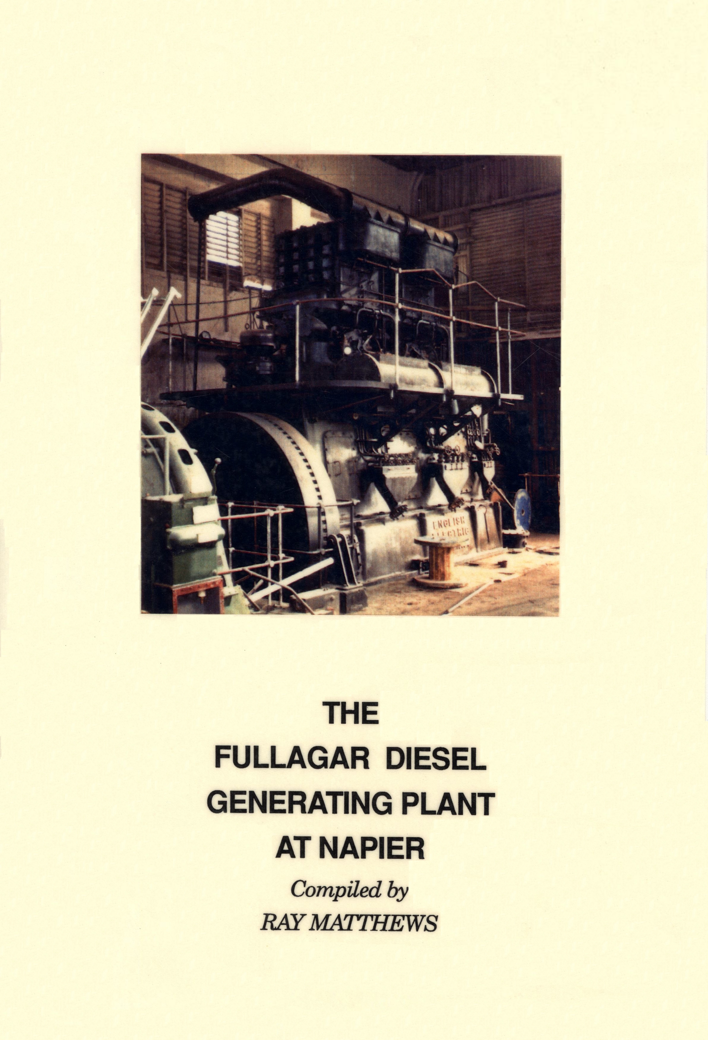
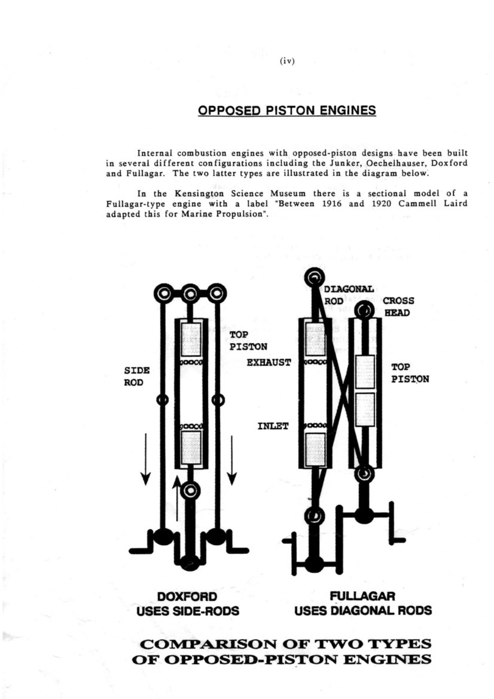
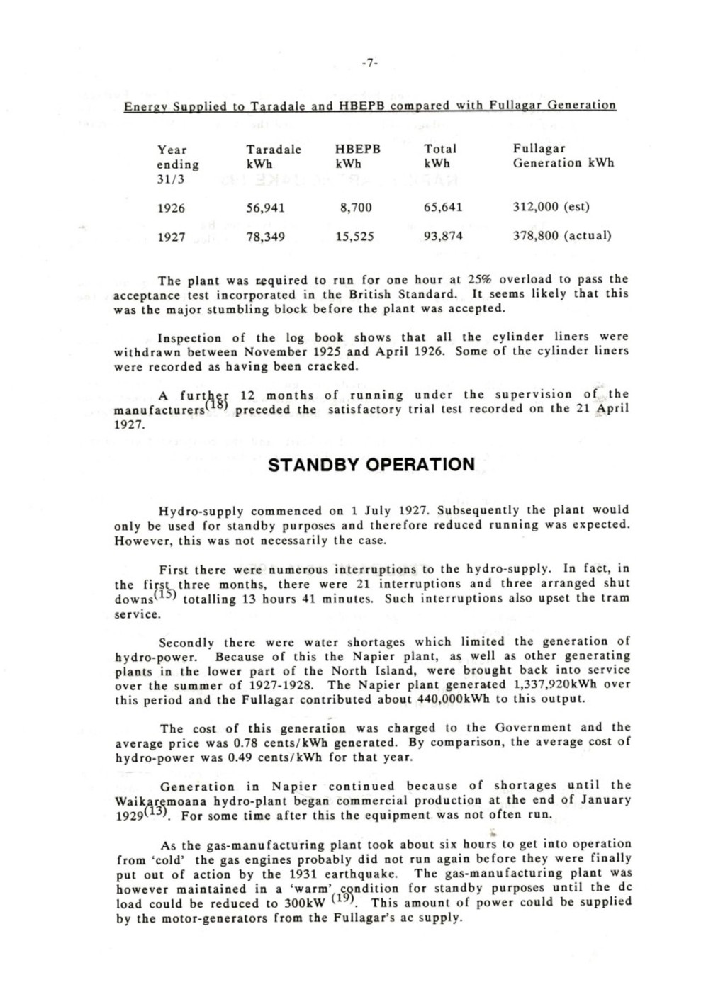
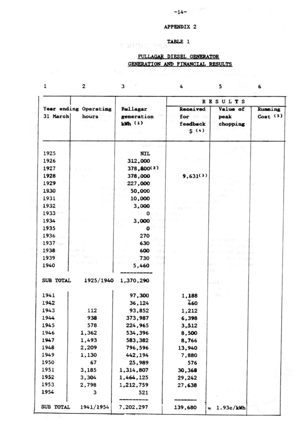
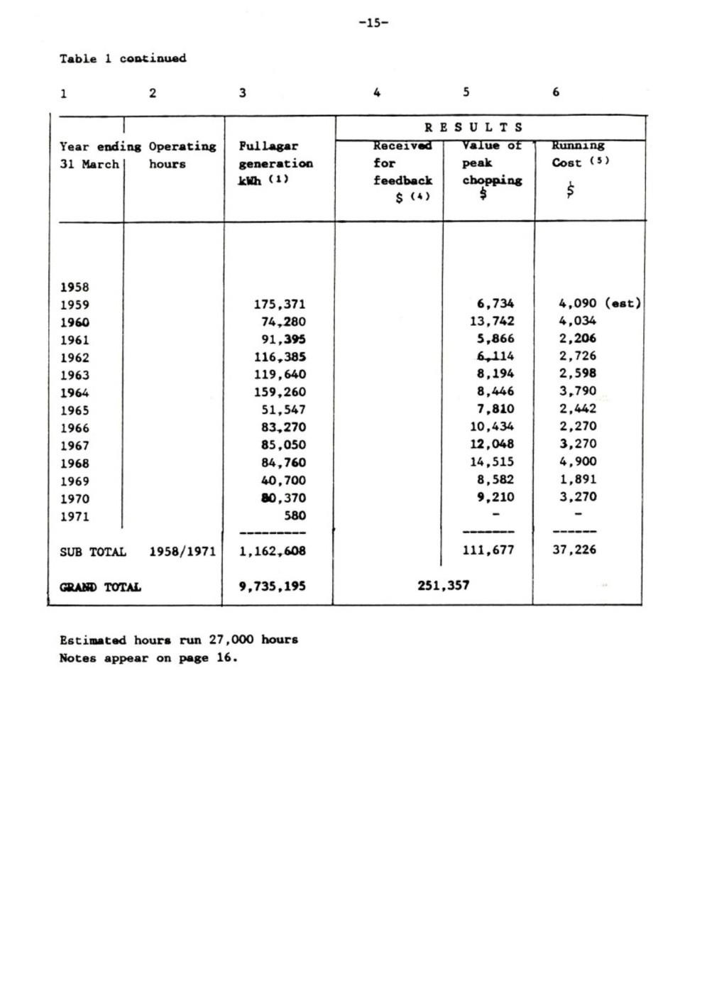
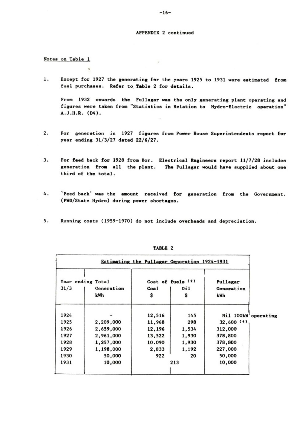
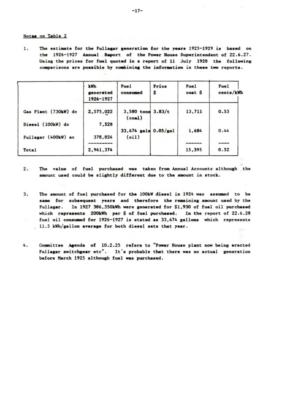
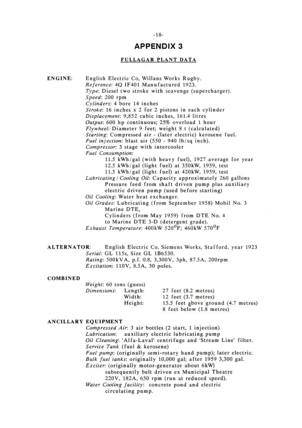
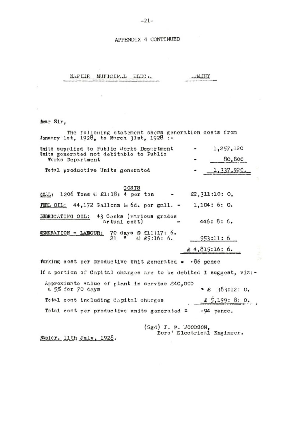
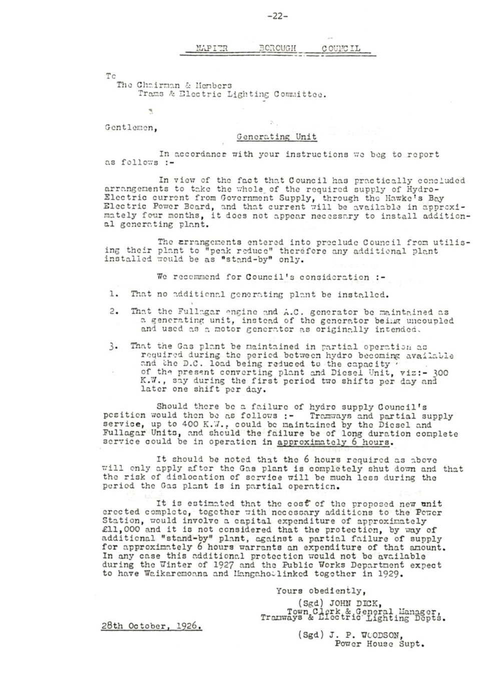
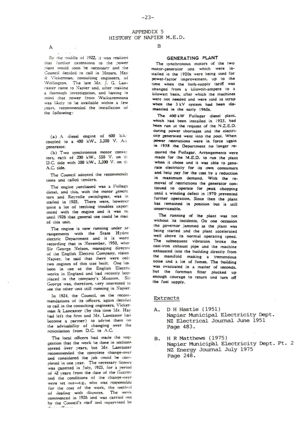
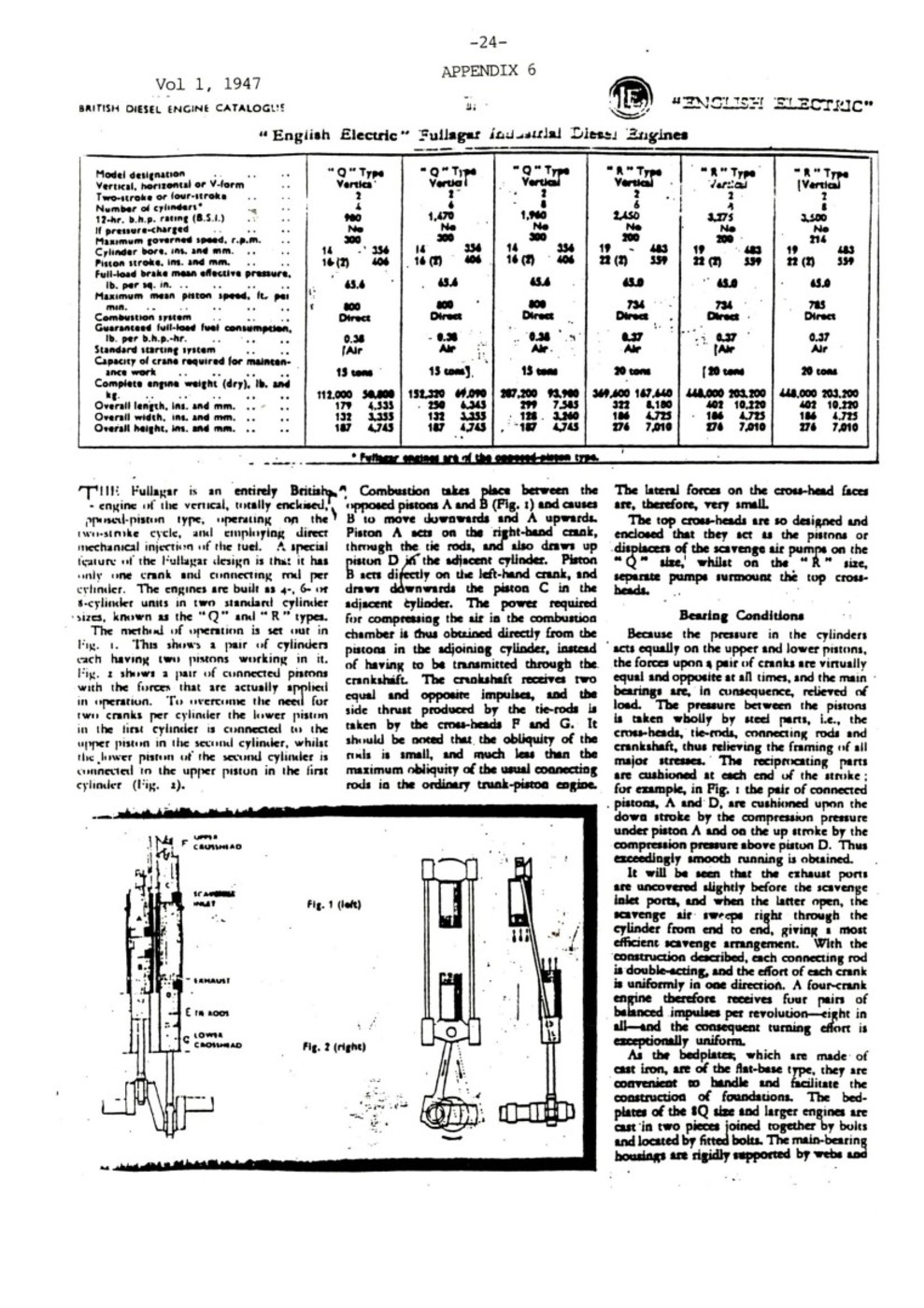
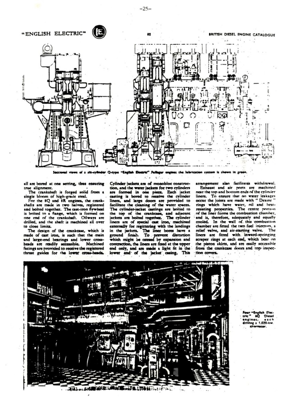
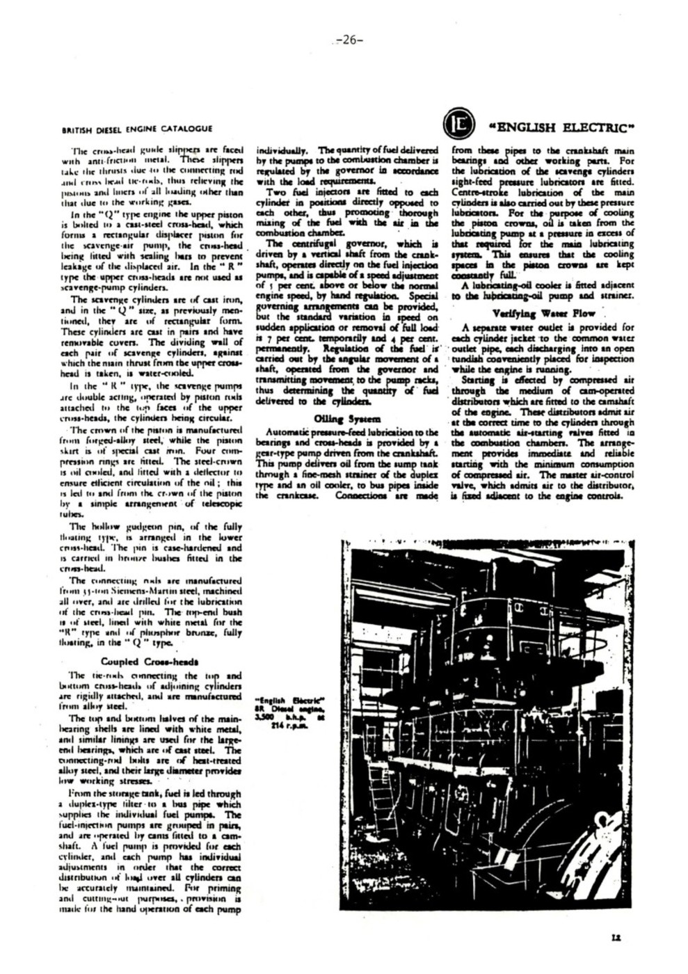
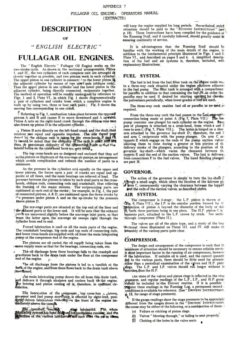
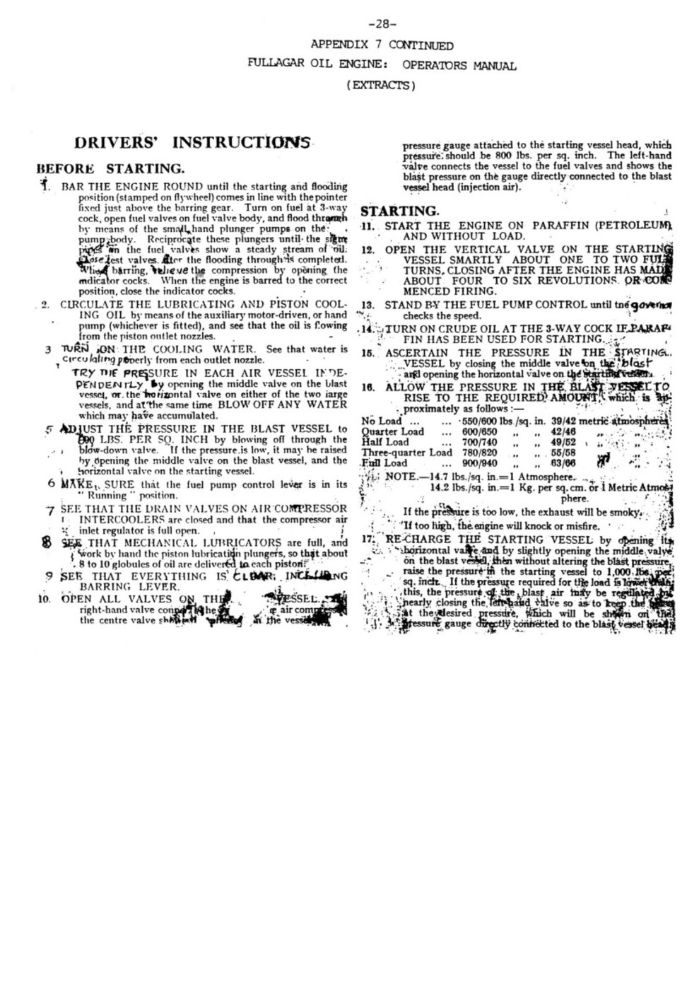
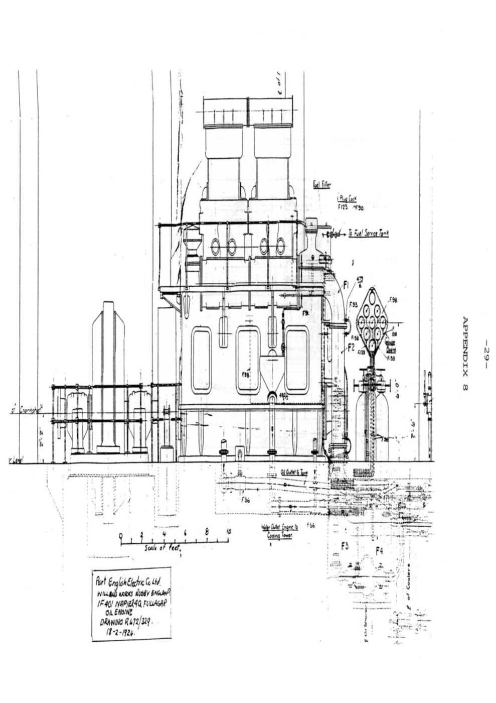
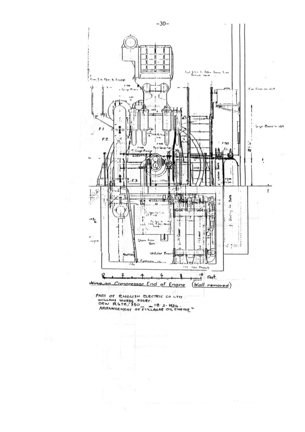
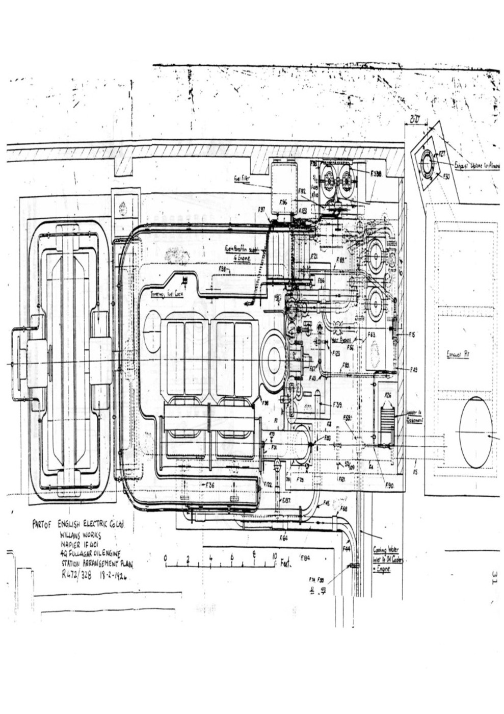
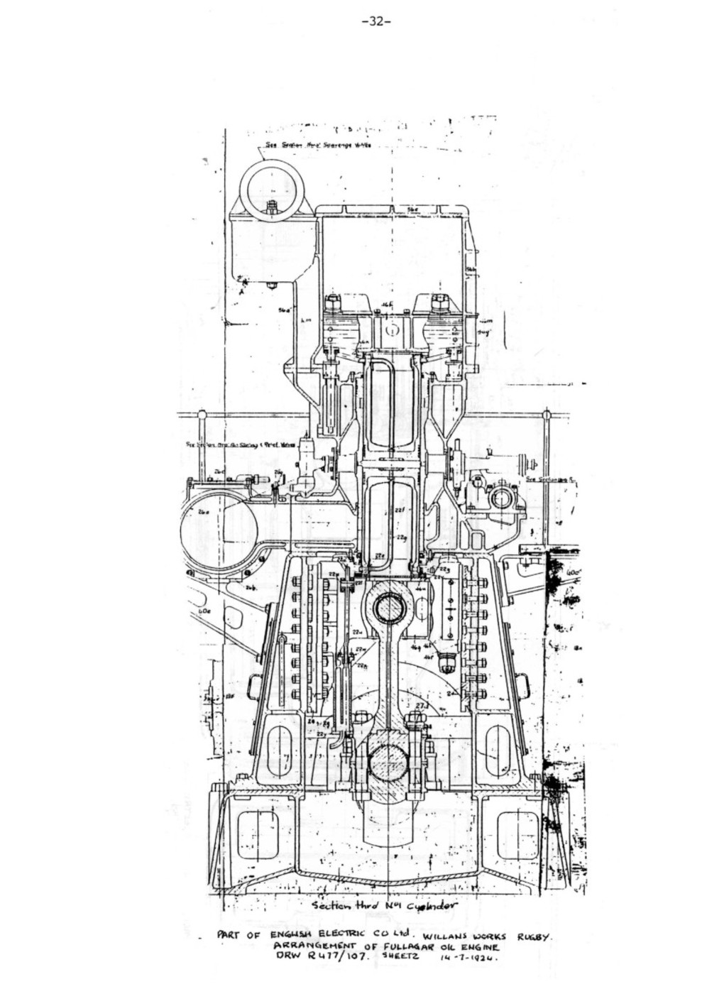
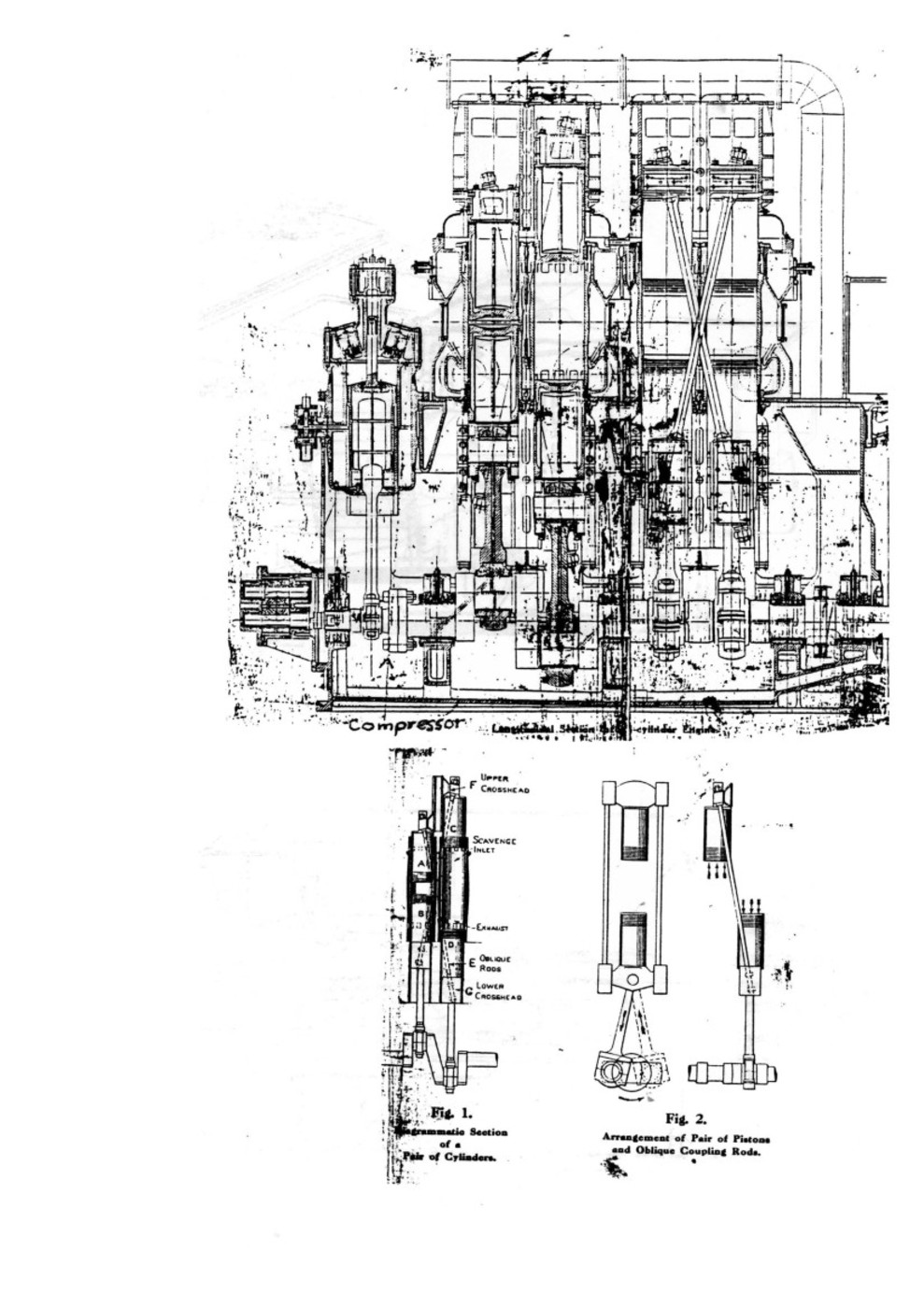
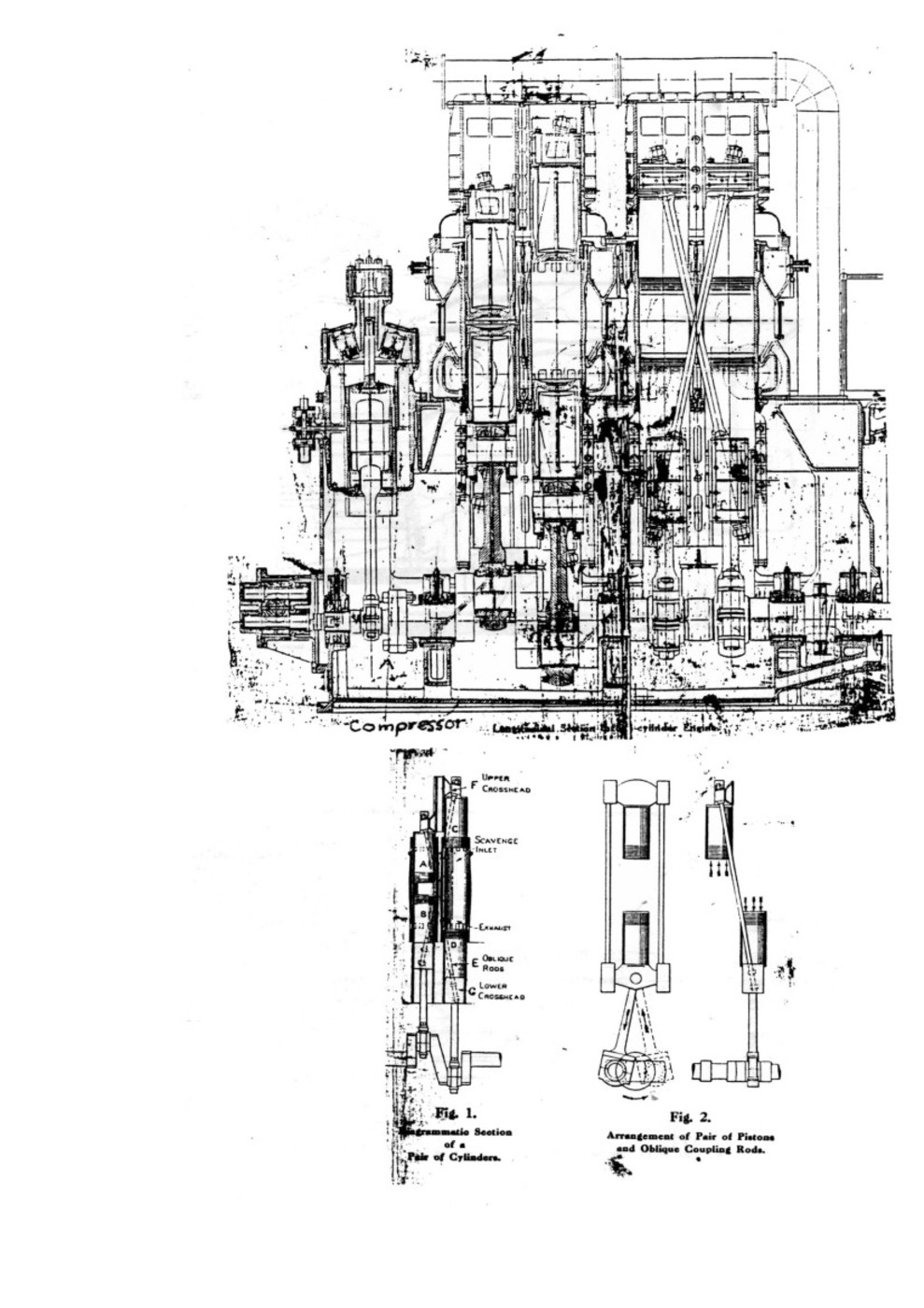
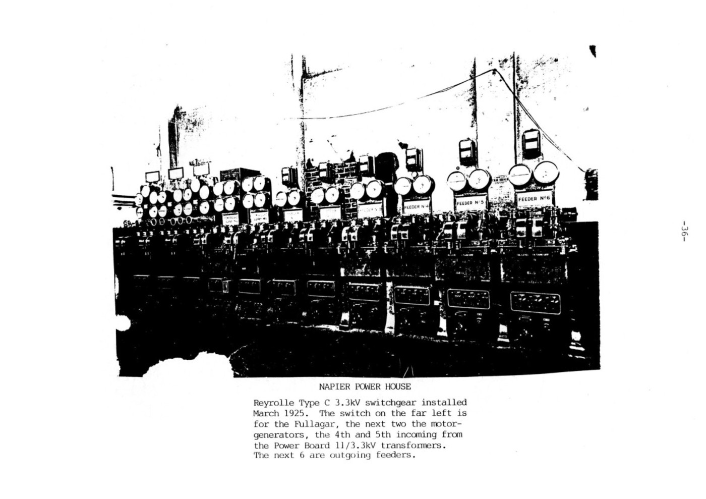
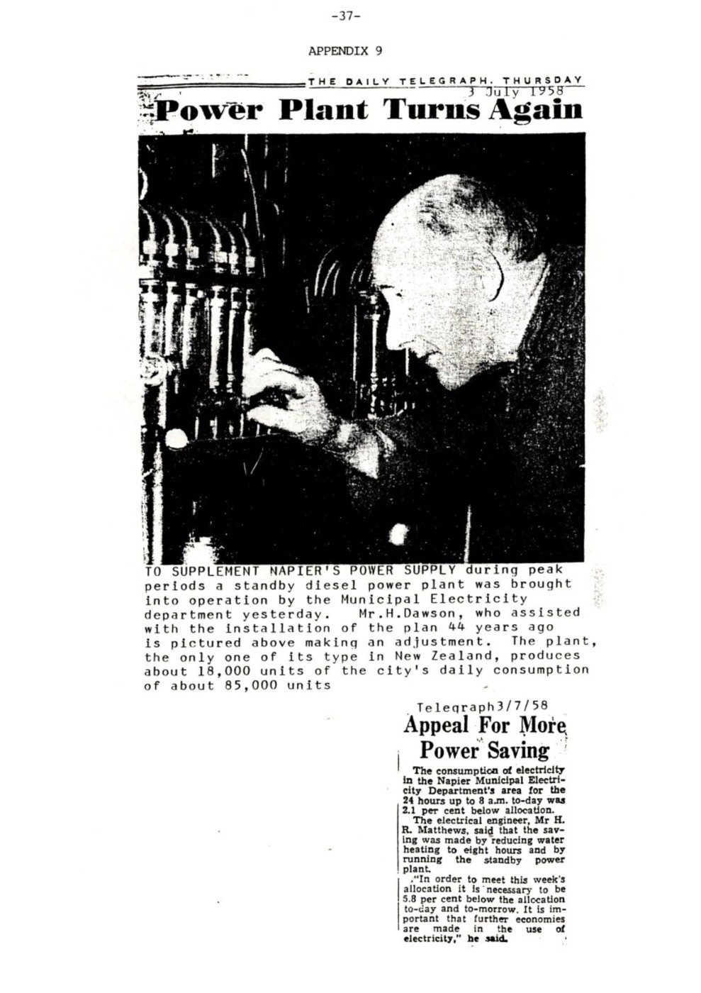
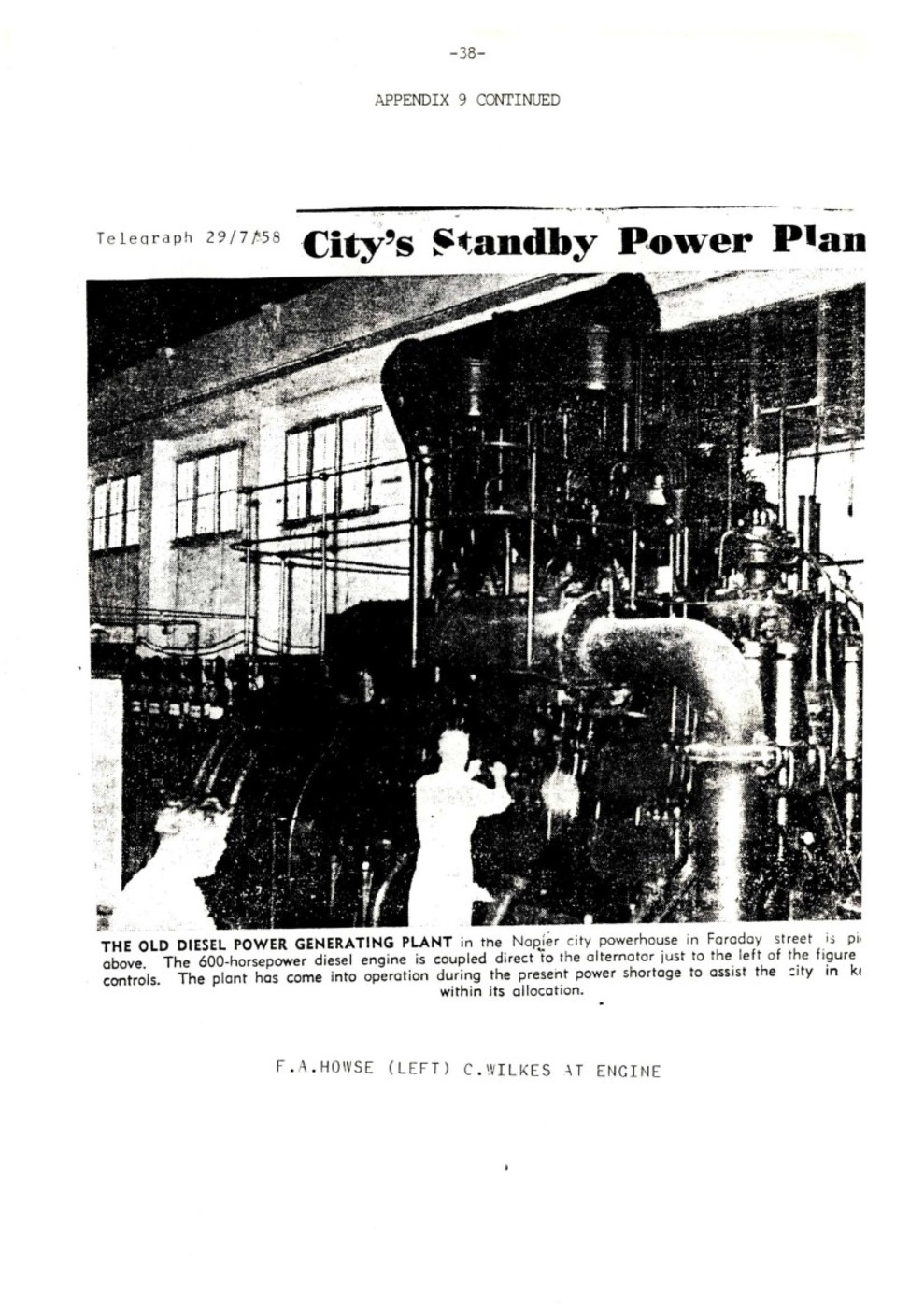
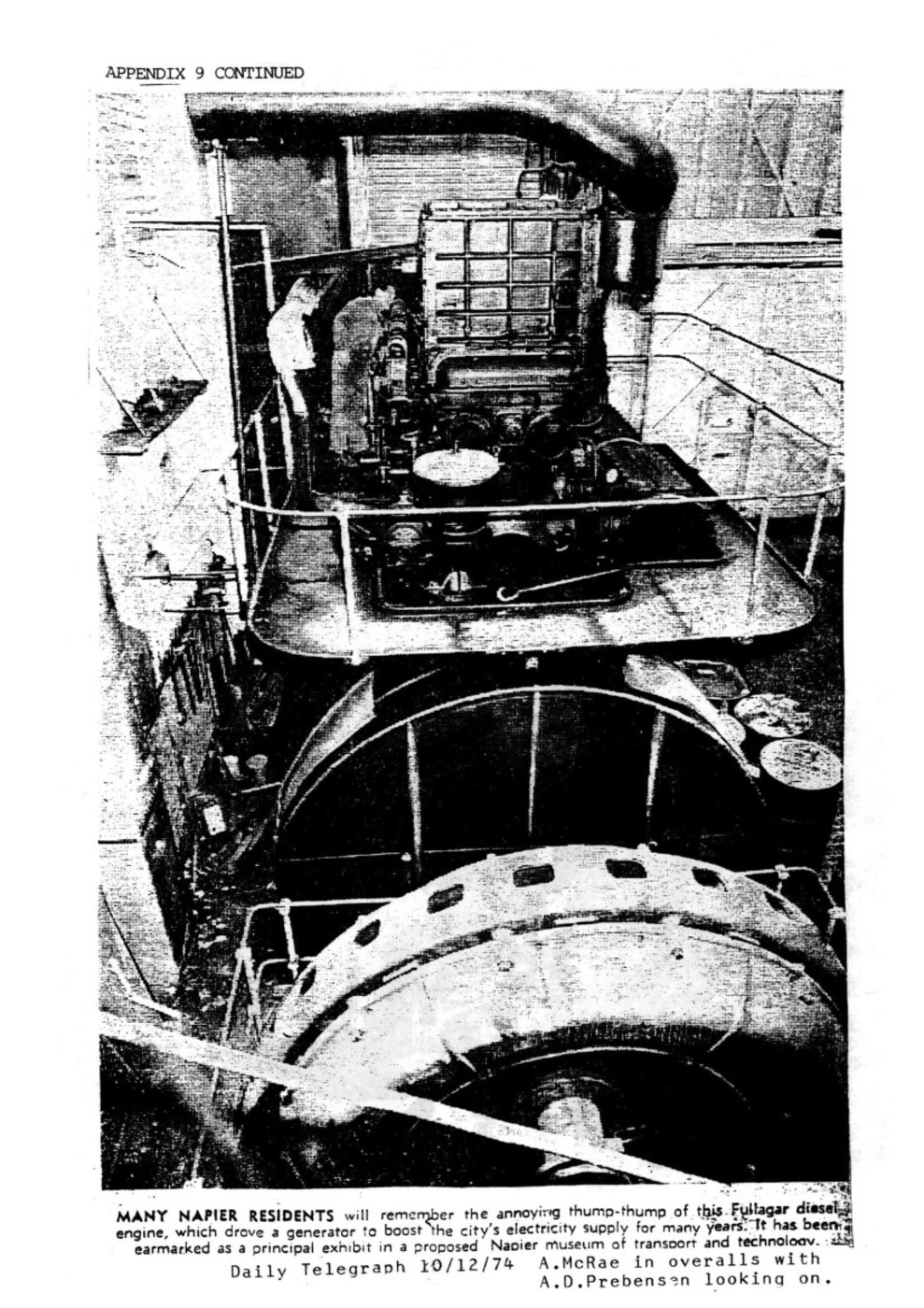
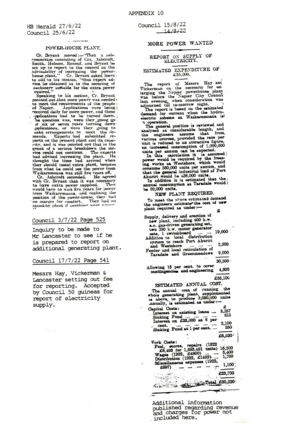
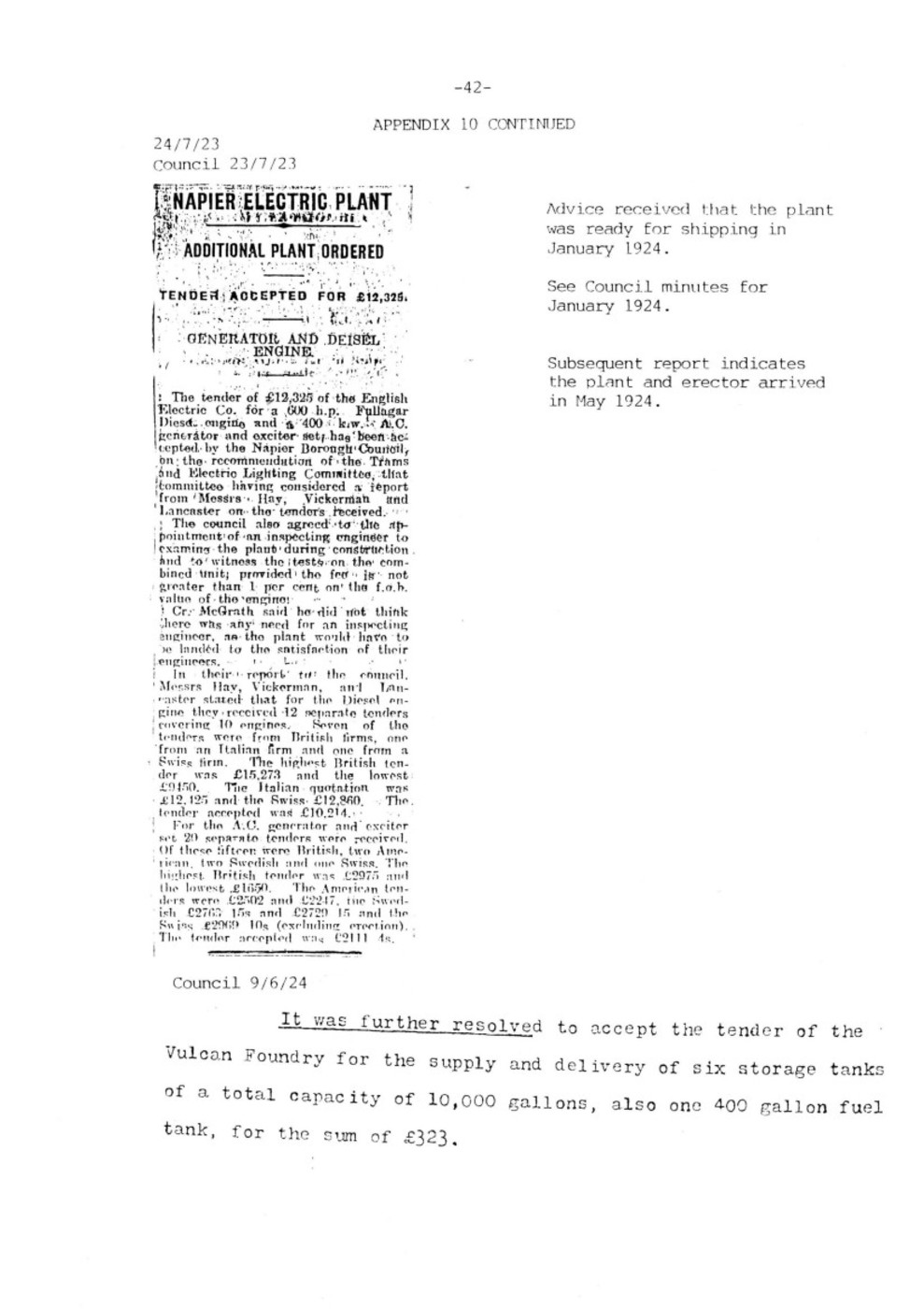
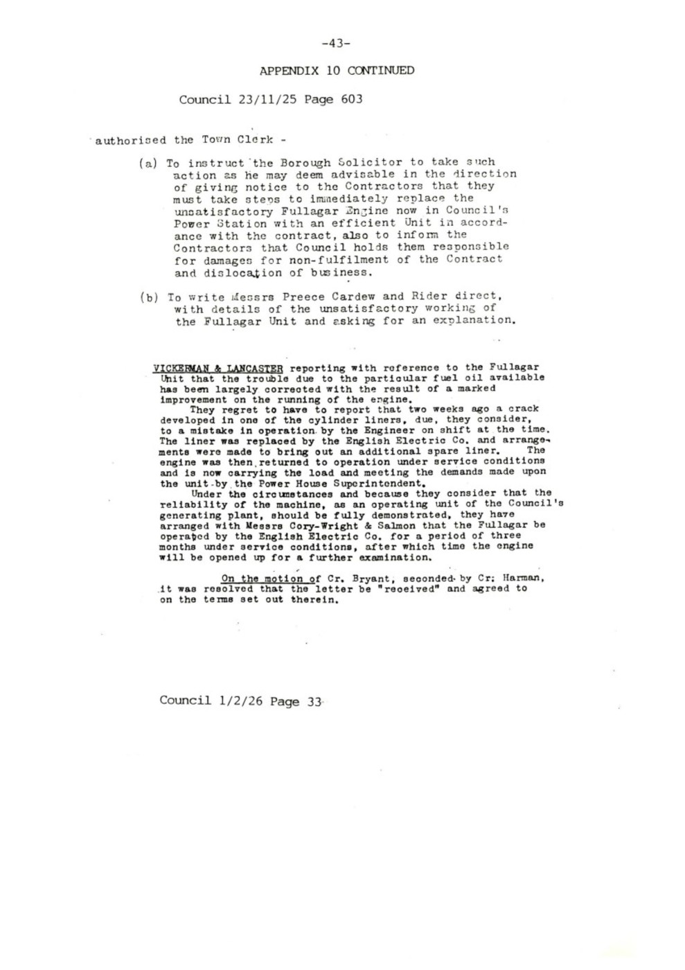
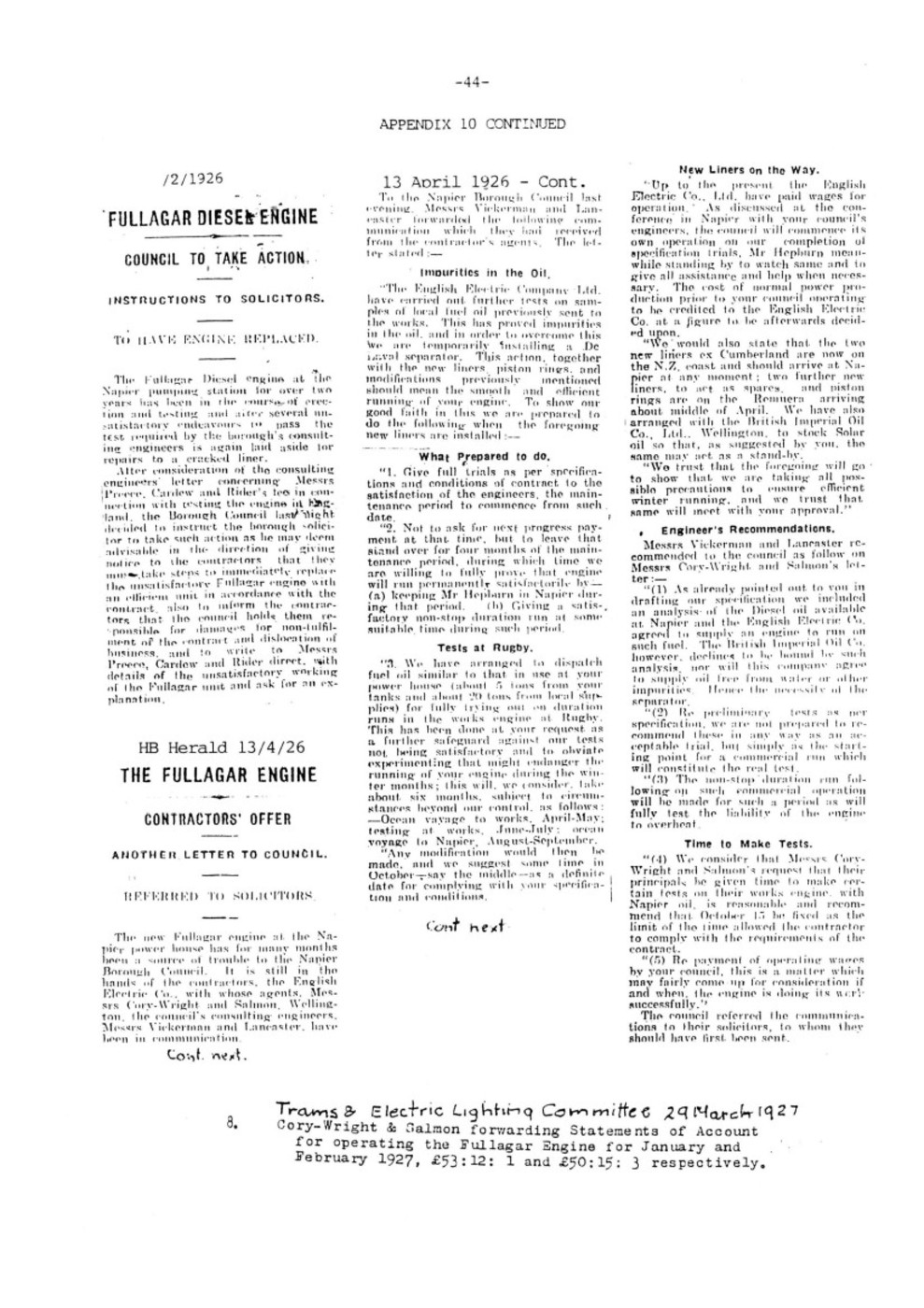
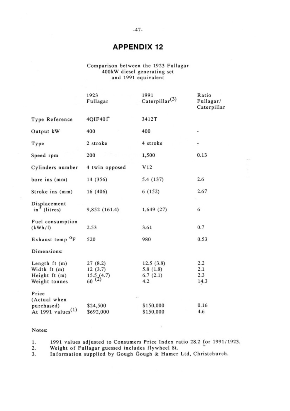
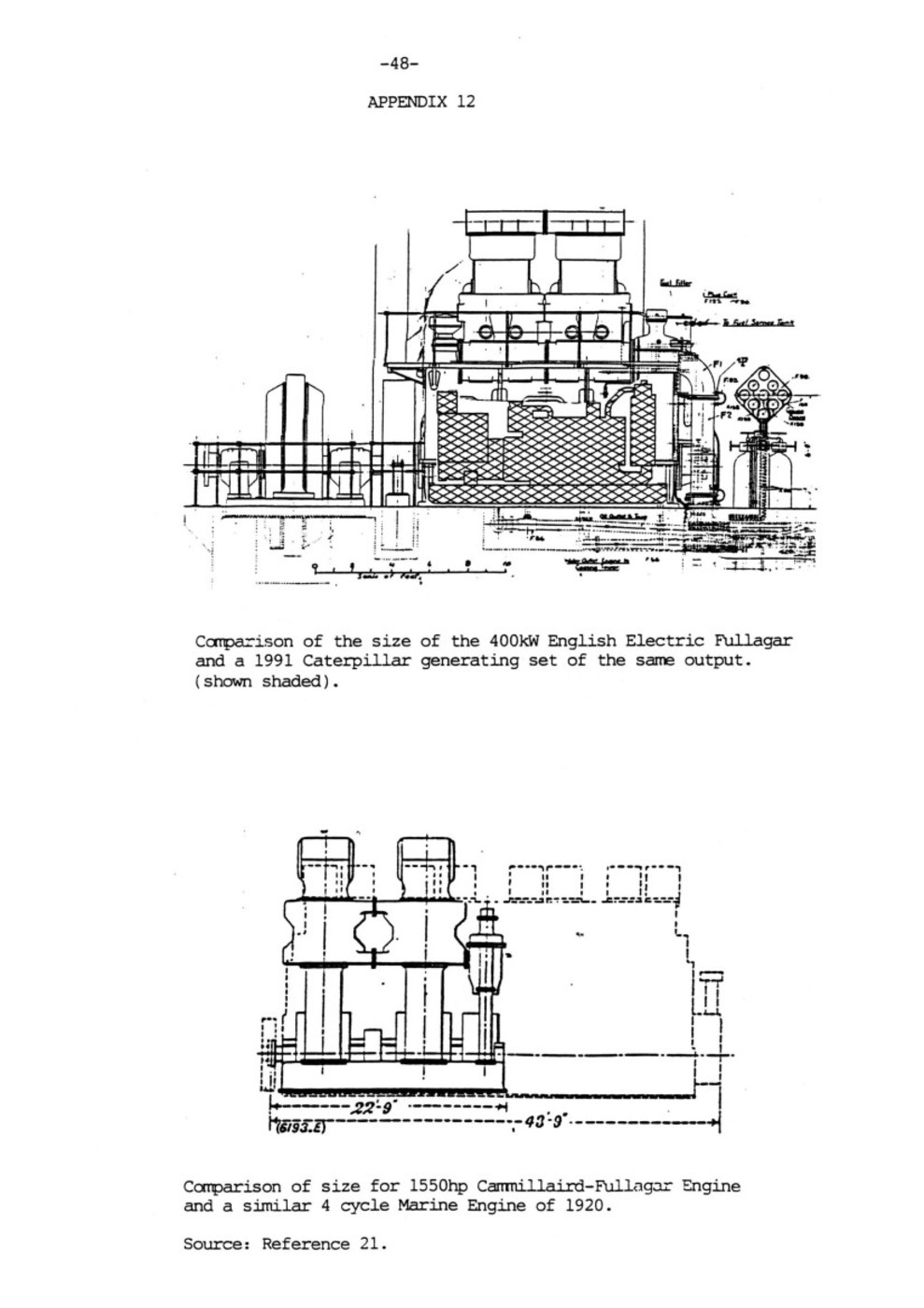
– 49 –
APPENDIX 13
THE ENGLISH ELECTRIC CO LTD
The English Electric Co Ltd was established in 1919 with a registered capital of five million pounds (25).
The following were the principal works which formed the core of the English Electric Co.
Name Location Specialty
Ordnance Coventry Munitions
Dick Kerr Preston Electric Traction
Phoenix Bradford Alternators & Motors
Willans Rugby Engines & Turbines
Siemens Stafford Heavy Electrical Plant
The Head Office was at Queen’s House, Kingsway, London.
Dick Kerr: established in 1875 was involved in Tramway and Railway electrification.
Prior to the formation of English Electric, Dick Kerr had already acquired the following companies:
(1) Willans & Robinson of Rugby in 1916
(2) United Electric Car Co of Preston in 1917
(3) The British subsidiary of the German AEG
(4) Phoenix Dynamo Manufacturing Co of Bradford in 1918.
Immediately after its formation, English Electric bought the Siemens Dynamo Works at Stafford from the Government which had compulsorily acquired it during the War from its German owners. The alternator for the Napier plant was manufactured at this plant.
Willans & Robinson: which became engine manufacturing arm of English Electric was founded in 1880. The company initially built marine engines and steam launches and then made central-valve engines designed for direct coupling to electric generators. They supplied one of New Zealands earliest generating sets to the Lyttleton Harbour Board in 1892.
Willans & Robinson also manufactured the 150 hp diesel generator (No. D78) which was purchased from the Miramar Borough Council in 1916. It operated in the Napier Power House until 1934 when it was sold to the North Auckland Kauri Timber Company. This unit was recorded as giving wonderful service (1).

– 50 –
Fullagar Engine Manufacture: In 1920, English Electric was licensed by Cammell Laird and the Fullagar Engine Syndicate to manufacture stationary engines of the Fullagar type. This was done at the Willans Works, Rugby under the leadership of J M Ferguson assisted by G H Paulin.
In 1922 the first Fullagar engine (No. D200) was built. It was used at the Willans Works power house 27 until 1950 and is the twin of the Napier plant. It was displayed on the lawn outside the works at Newbold Road, Rugby until it was scrapped about 1979 or 1980. This was despite the efforts by Mr Robert Cox 27 to have the plant preserved.
By 1930, 36 engines had been built. These had a 14 inch bore and 16 inch stroke. The output was either 750, 1125 or 1500 hp depending on whether the engine had 4, 6 or 8 cylinders 26. Larger engines were manufactured from 1930 onwards in various sizes up to 3500 hp and the production of Fullagar engines continued until the 1950’s.
About 150 Fullagar engines were produced by English Electric of these 8 were supplied to Bermuda 27. If any other Fullagar engine is still in existence it would likely to be in Bermuda.
In 1969, English Electric was merged with GEC (General Electric Co of UK).

– 51 –
Appendix 13 Continued
HF FULLAGAR MA OF NEWCASTLE-ON-TYNE
Hugh Francis Fullagar (1872-1916) was the originator of the idea of using diagonal connecting rods on opposed-piston internal combustion engines. The rationale was described in his paper published by the Institution of Mechanical Engineers (London) (23) in 1914. A ship named “Fullagar” was launched in February 1920 and is described in IMech E Proceedings in 1922.
Reference is made to a “Fullagar Engine Syndicate” which presumably owned the patent and licenced manufacturers to produce the engine.
His death in London on 31 December 1916, was before any Fullagar-type engines, were manufactured commercially. An obituary (28) and biographical notes (29) of Mr Fullagar and his father appear below:
The death of HUGH FRANCIS FULLAGAR at the early age of 44 has removed one of those best qualified to uphold the title of engineer, and a man who combined with the zeal of a pioneer a grasp of fundamental principles which caused his work to advance along scientific rather than rule-of-thumb lines.
He began his career by serving his time with Messrs. Sturgess & Towlson, of Norwich who were then the principal firm of general engineers in the city. While still apprentice he was frequently sent out in charge of important repairs and undertook work of considerable responsibility. In 1894 he went up to Cambridge and took the Mechanical Science Tripos, and was also assistant in research work to Sir J. A. Ewing, at that time Professor of Engineering at the University.
The greater attraction always lay for him in coming developments rather than along well worn grooves and in 1897 he joined Messrs. C. A. Parsons & Co., Ltd. At that date a 500 K.W. set was considered a large machine and Mr. Fullagar was responsible for a number of improvements in the construction of steam turbines, many of which are still in common use. He was associated with the introduction of the first turbine set into what is now the network of electric power supply spreading over the North of England, and as consultant on turbines to Messrs. Merz & McLellan ever since maintained his connexion with this development. Leaving Messrs. Parsons he became responsible for the design of the first large turbine, a 5,000 K.W. built in America, and at the invitation of the Allis-Chalmers Company visited the States in 1904 to advise the firm on the construction of their new works for turbine manufacture.
The problems of the gas turbine then demanded his attention and he carried out considerable research work upon it. His method was always to set himself an exceedingly high standard and then to investigate and eliminate or overcome the causes normally preventing its attainment, but Mr. Fullagar had reluctantly to admit that materials were against the gas turbine of high efficiency, and he then turned his attention to the new type of gas engine which bears his name and the root idea of which had occurred to him some little time previously. The Fullagar engine was intended primarily to reduce weight and space occupied, and consequently cost, as compared with the continental type of gas engine, to reduce the number of moving parts and secure almost perfect balance, and it has also attained excellent thermal efficiency.
A 500 horse-power engine was built and erected at Gateshead and formed the subject of a visit by members on the occasion of the Joint Meeting of the Institution of Naval Architects, the Institution of Engineers and Shipbuilders in Scotland and the North East Coast Institution of Engineers and Shipbuilders at Newcastle-upon-Tyne in July, 1914, while papers on the system were also read and discussed, and are contained in Vol. XXX of the Transactions. At the time of his death he had completed the design of a 2,000 horse-power set, the first British gas engine of this power, which is now being installed in a north country power station. Further development of the Fullagar engine to submarine merchant service, aeroplane and motor car work has been somewhat delayed by the war, but Mr. Fullagar had large minded ideas of future progress and his many friends experience keen regret that he has not been permitted to witness their fruition.
Mr. Fullagar was elected a Member of the Institution in 1912. He took a keen interest in its work and was always ready to render assistance and support.
Sources: Reference 28 & 29.
FULLAGAR HUGH FRANCIS. Adm. Pens. at ST JOHN’s, Oct. 5, 1894. Of Warwickshire. S. of Hugh Scales (next), R. Of Hunworth and Stody, Norfolk (and Mary Louisa Prynne Hawkes). B. Jan. 1, 1872, at Meriden. Matric. Michs, 1894; B.A. 1897; M.A. 1907. Mechanical Engineer; specialized in gas engines. Of Park Head, Jesmond Dene, Newcastle-upon-Tyne. Died Dec. 31, 1916, in London. Brother of Lewis H. (1887). (Scott, MSS.; The Times, Jan. 5. 1917.)
FULLAGAR, HUGH SCALES. ” Adm. pens. at Caius, Jan 12, 1854. S. of John Edward, solicitor, of Lewes, Sussex. B. There (Jan. 9), 1836. Matric. Michs. 1854; Scholar, 1855-8; B.A. 1858; M.A. 1863, Adm., Com. causa, at Oxford, Feb. 19, 1863. Ord. deacon (Oxford) 1860; priest, 1862; C. of Over Winchendon, Bucks., 1860-3. C. of Packington, Warws., 1867-72. C. of Erpingham, Norfolk, 1872-81. R. of Hunworth and Stody, 1881-1928. Died Jan. 14, 1928, at Hunworth. Father of the above and the next (Venn, 11. 315 and addenda; Crockford; Al. Oxon.)

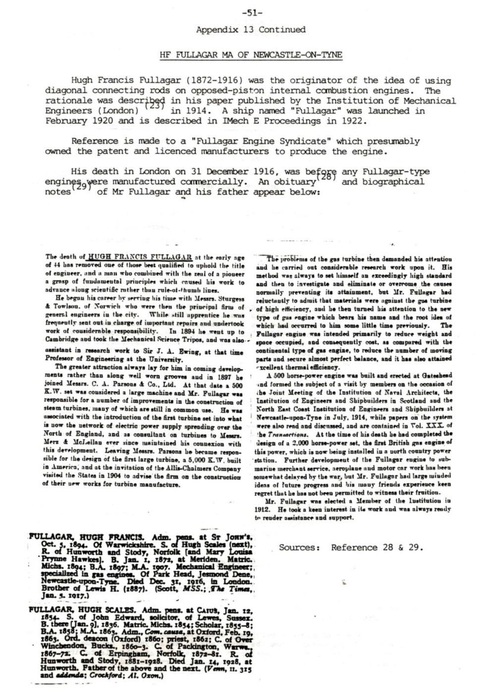
– 52 –
APPENDIX 14
OFFICERS REPORTS FILE P 220
HRM:GM E4/4/1
S3/1
4th February 1971.
The Town Clerk,
NAPIER.
RELIABILITY OF SUPPLY AND STANDBY GENERATOR REPLACEMENT
The standby generator has been unserviceable for some months because of faulty insulation on the stator winding, and the cost of re-winding the machine is in excess of $11 000. This report covers some of the points which the Electricity Committee will need to consider regarding its repair or replacement.
It is not recommended that repair work be undertaken but that further investigation be given to replacing it with a second-hand machine if one becomes available shortly or by purchasing a new one, which could cost about $45 000.
BRIEF HISTORY:
The 400 kW standby Fullagar diesel generator was installed for the cost of $25 000 in 1925. This was two years before hydro power was available, and the machine has been maintained in a serviceable condition for standby use since 1927. During electricity restrictions (1940-1953) it was operated at the expense of the New Zealand Electricity Department, who purchased the power generated. Since 1958, when the N.Z.E.D. no longer required the operation of the generator, it has been run by the M.E.D. during the 1958-59 restrictions and after that to cut peak power, thus saving on the purchase price of electricity.
ECONOMICS OF OPERATION:
In order to reduce the maximum demand, it has been necessary to run the plant approximately 200 hours per year. This has cost less than the calculated value of the reduction in our purchase price of power, and the calculated savings over the last three years are as follows:-
1967 – $7 351
1968 – $8 582
1969 – $9 210
If a new plant were purchased it is possible that the operating costs would be less, and for the same sized generator the savings could be greater than those above. For an expenditure of $45 000 it is likely that a return of 15 to 20% per annum could be reasonably expected.
DIFFICULTIES WITH OBTAINING NEW PLANT:
Some years ago when I made an enquiry with the New Zealand Electricity Department regarding the operation of a larger replacement plant, I was told by the then Assistant General Manager that in his opinion the contract which the N.Z.E.D. have with the Power Board provides for the operation of our existing plant and not necessarily another plant.
If a new plant were purchased from overseas an import licence would be needed. I understand from the suppliers of this type of equipment that there is no problem about an import licence, but standby plants are normally required for standby for essential services and not for the generation of electricity for public supply.

– 53 –
NEED FOR STANDBY PLANT:
The need for standby plant for essential City services is one which is also to be related to the reliability of our supply, and this subject will be dealt with in the next section. A standby plant for essential services, in my opinion, essentially requires a plant to be transportable. The size envisaged could relatively easily be made to be transportable and taken to a site in an emergency to supply power for pumping water, sewerage or stormwater. Under these conditions, however, I would estimate that a delay of one to two hours could be expected. If the plant could be used for peak load-cutting and also be available for emergency services, this second use is therefore available at no extra cost.
RELIABILITY OF SUPPLY:
This can be discussed only briefly, and the main points are classified under the headings which, follow:-
(1) Inadequate N.Z.E.D. generating capacity: In the case of insufficient generating capacity on the N.Z.E.D. system, our own plant (if the same size as the present machine) could supply only 3% of our power requirements and if run 24 hours daily would supply less than 5% of the energy requirements in the winter months. Adequate planning should avoid the possibility of this occurring.
(2) N.Z.E.D. transmission and bulk supply substation failure:
In the last ten years there have been two supply failures exceeding 30 minutes. In 1961/62 there was a failure for 70 minutes and on 24th September 1970 two successive failures resulted in a loss of supply for 39 minutes.
With further interconnection before 1975 by way of a 220 kV transmission line from Wairakei to an additional N.Z.E.D. bulk supply substation north of Napier, the security of supply from the N.Z.E.D. system should be at least as good in future as it has been in the past. (Refer map page 9.)
(3) 33kV Sub-Transmission on 33/11 kV substations:
Two interruptions to the supply between Redclyffe and Napier exceeding half-hour duration in the last ten years were:-
15.4.62 2hrs. 8 mins. Trees interfering with 33 kV lines in high wind.
27.12.66 1hr. 31 mins. Protection operated incorrectly.
(a) Since 1967 there have been four lines between Redclyffe and the H.B.E.P.B. substation at Onekawa, and it is hoped that a large number of short irritating interruptions which have occurred in recent years will be eliminated in future.
(b) The most vulnerable part of the system is the double circuit 33 kV line from Onekawa to the Power House, Faraday Street, via Taradale Road and the railway line. A fault affecting both circuits could cause an outage of some magnitude. Fortunately there are two 11 kV interconnections with the H.B.E.P.B. ll kV system which could be used to supply essential load from the H.B.E.P.B. substation at Marewa. A third connection at McGrath Street/Te Awa Avenue could be made in the future to increase the amount of power which could be transferred at 11 kV.
(c) The 11 kV switchgear at the Power House which has caused a number of minor interruptions to the supply in the past will not have such a vital function in future when an additional 33/11 kV substation is installed at Shakespeare Road. For a number of years in future, supply could be transferred to Bluff Hill Substation in an emergency when it has been commissioned in approximately two years’ time.

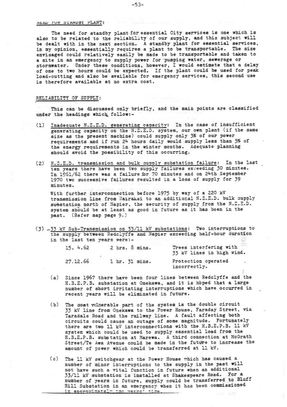
– 54 –
RELIABILITY OF SUPPLY AND STANDBY GENERATOR REPLACEMENT (contd. 3)
(c) (contd.) The diagram on page 10 shows the connections between Redclyffe and Napier.
The reliability of the supply under this heading could improve in future except for the 33 kV line between Onekawa substation and the Power House, for which no proposals are at present under consideration.
4. Faults on M.E.D. Distribution: With a few minor exceptions, outages exceeding one hour have been the result of storm damage and continued to one or two small areas where supply could not be restored until damage was repaired. Further progress on undergrounding should improve this situation in future. For many years there will be areas where small numbers of consumers may not be able to be supplied with power until repairs are complete. It is possible that there could be times when a transportable generating plant could be used to restore supply more quickly.
CONCLUSION:
Taking into account the above matters, the replacement of the standby plant to provide an emergency service for public supply is not practical, bearing in mind that a replacement machine of 400 to 500 kW would only provide about 3% of our maximum demand and could only provide for standby for some essential City services which would be best provided by transportable plant.
A replacement plant of approximately the same capacity could no doubt be installed and operated for peak load cutting at an economic advantage and provide a back-up for essential services at no extra cost. Accordingly, I would recommend that further investigation be given to the purchase of a replacement plant.
Yours faithfully,
H. R. MATTHEWS
City Electrical Engineer
Council P516
Minutes of the Electricity Committee 9 February 1971
Item 6
E4/4/1
S3/1
City Electrical Engineer re: Reliability of Supply and Standby Generator replacement. Reporting on the cost of repairs and replacement of the standby generator.
Committees Recommendation
That Council resolve to take no action at the moment but further investigation be made.
The recommendation was adopted by Council, Page 549.

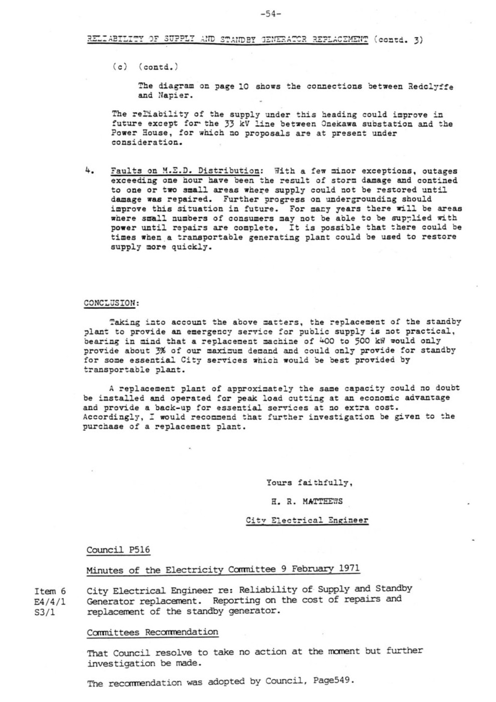
Original digital file
FaradayCentre3806_Fullagar.pdf
Non-commercial use

This work is licensed under a Attribution-NonCommercial 3.0 New Zealand (CC BY-NC 3.0 NZ).
Commercial Use
Please contact us for information about using this material commercially.Can you help?
The Hawke's Bay Knowledge Bank relies on donations to make this material available. Please consider making a donation towards preserving our local history.
Visit our donations page for more information.
Description
Surnames in this book –
Archer, Ashcroft, Axford, Baker, Bedford, Boyce, Bradley, Bryant, Cory-Wright, Cox, Dark, Dawson, Densham, Dick, Evans, Fullagar, Goodger, Gordon, Hands, Harman, Harris, Hastie, Hawker, Hepburn, Hindmarsh, Howse, Isles, Lancaster, Larrington, Marcroft, Martin, Matthews, McFarlane, McGrath, McLeod, McRae, Metcalf, Nelson, Owen, Prebensen, Renouf, Roddick, Sant, Sheilds, Smith, Stewart, Sullivan, Symons, Thurston, Walton, Webster, Wilkes, Woodson
Subjects
Format of the original
Book boundDate published
October 1991Accession number
616354Supporters and sponsors
We sincerely thank the following businesses and organisations for their support.


Do you know something about this record?
Please note we cannot verify the accuracy of any information posted by the community.